Hardware Installation—Installing the IFC-1010/2020
37
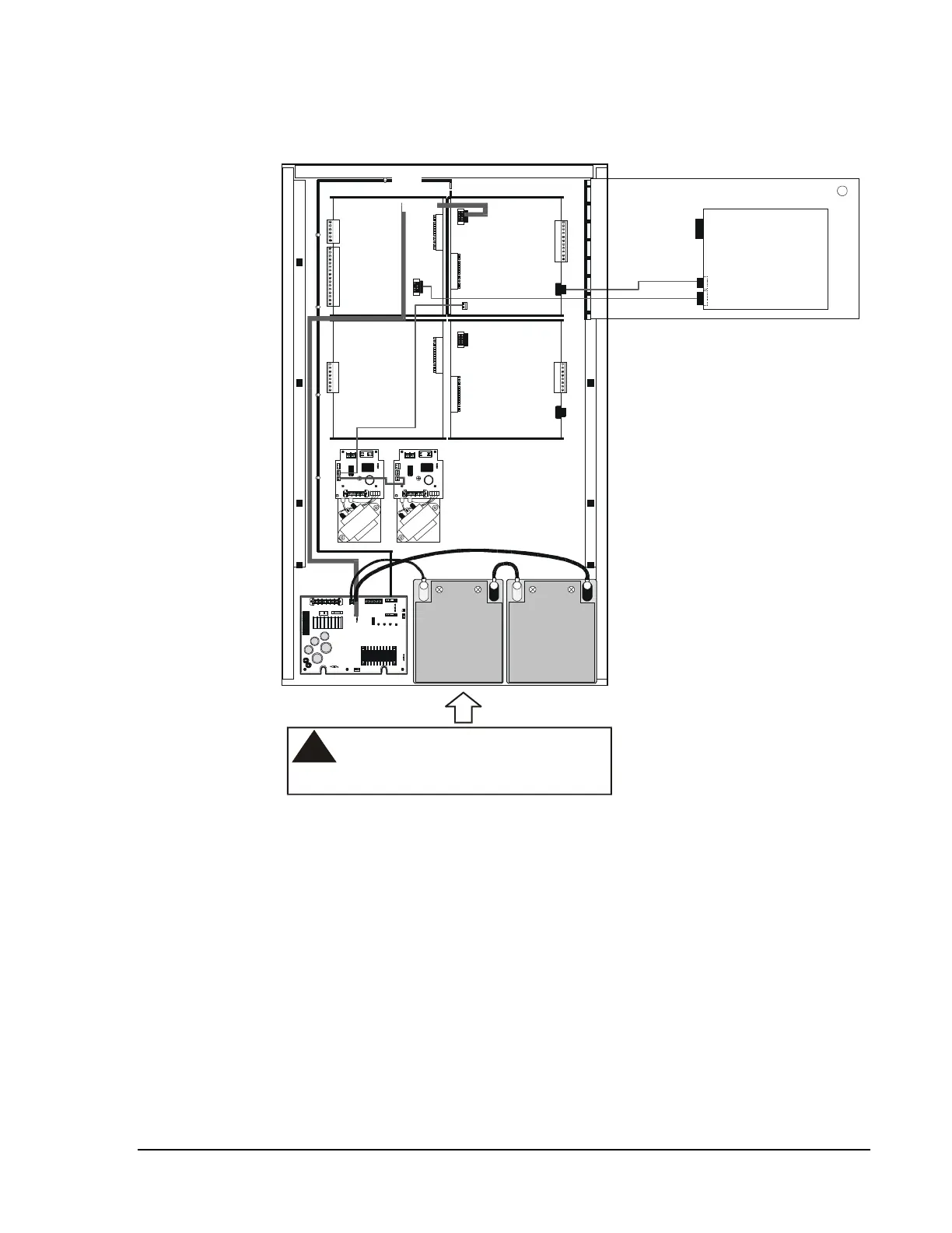
Figure 29 depicts system wiring placement.
!
CAUTION:
Be sure to allow for BP-3 Battery
Dress Panel screw clearance
between batteries here.
1 21 2 3 4 5 6 7 8
1 2 3 4 5 6
wireplac
1
2
3
4
5
6
7
8
1
2
3
4
5
6
7
8
1
2
3
4
5
6
7
8
9
10
11
12
13
14
15
16
11
10
9
8
7
6
5
4
3
2
1
P4
P2
P4
P3
P3
P5
P2
P5
SIB-2048A
or
SIB-NET
CPU-2
or
CPU-2020
1
2
3
4
5
6
TB1
P3
P4
LIB-200 LIB-200
MPS-24A/E
DIA
DIA-1010
or
DIA-2020
71030
(to ICA)
A
P
S
-
6
R
A
P
S
-
6
R
71071
Battery Battery
71072
71070
71033
71046
71031
75226
Figure 29: Wiring Placement Diagram
Note: The battery charger output is not power-limited. All wiring
connected to these terminals must remain at least 6.35 mm
(0.25 inch) from all power-limited wiring. Refer to Figure 30.