Note: See Input and Output wiring guidelines to
determine wire size and cable lengths for cables
other than the recommended cables.
Note: The FC Bus and SA Bus wiring
recommendations in this table are for MS/TP
Bus communications at 38.4k baud. For more
information, refer to the MS/TP Communications Bus
Technical Bulletin (LIT-12011034).
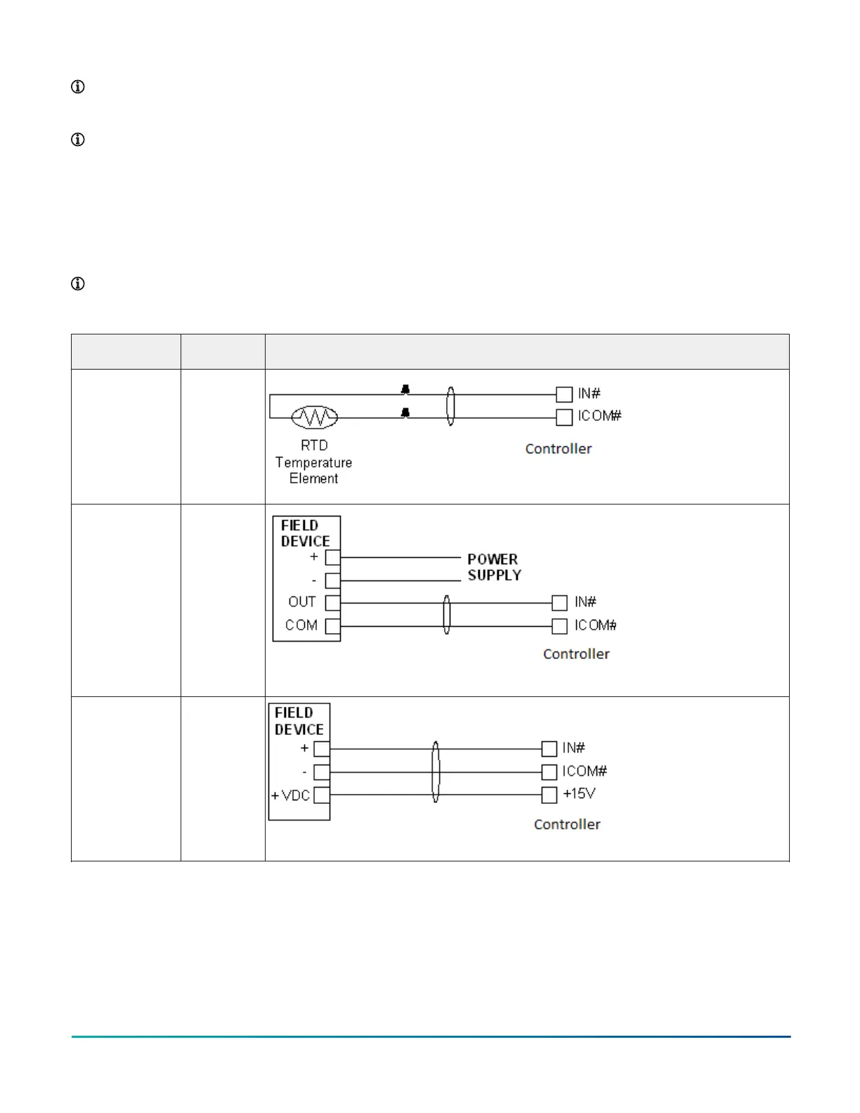
Termination diagrams
A set of Johnson Controls termination diagrams provides details for wiring inputs and outputs to the controllers. See the
figures in this section for the applicable termination diagrams.
Note: The CGM04060 and CGE04060 models do not have analog outputs. References to the analog output apply to
the CGM09090 and CGE09090 models only.
Table 6: Termination details
Type of field
device
Type of Input/
Output
Termination diagrams
Temperature
Sensor
UI
Voltage Input -
External Source
UI
Voltage Input -
Internal Source
UI
M4-CG Series General Purpose Application Controller Installation Guide 11

 Loading...


