Physical features
The following figures display the physical features of the
CGM and CGE controllers, and the accompanying table
provides a description of the physical features and a
reference to further information where required.
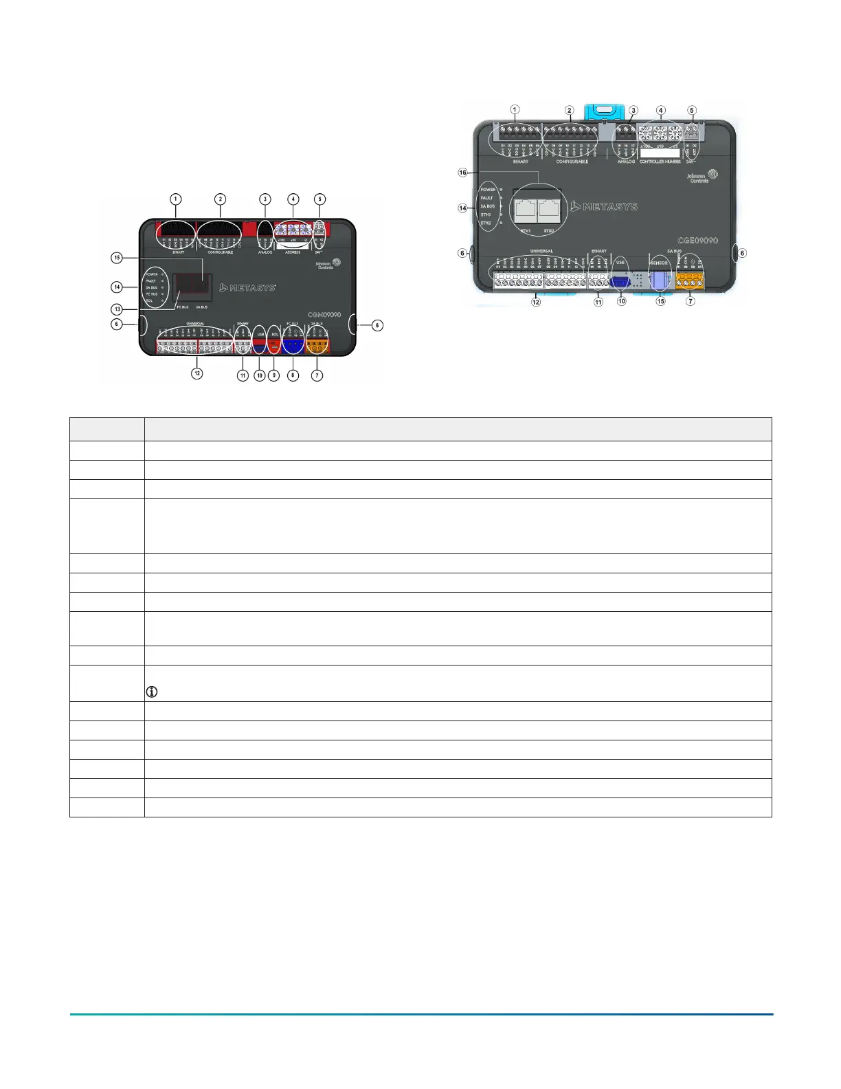
Figure 1: CGM Physical Features
Figure 2: CGE Physical Features
Table 1: Physical features of CGx series controllers
Physical Feature: Description and References
1 Binary Outputs (BO) Terminal Block: Black terminals. See Table 3.
2 Configurable Outputs (CO) Terminal Block: Black terminals. See Table 3.
3 Analog Output (AO) Terminal Block: Black terminals. Only present on CGM09090 and CGE09090 models. See Table 3.
4 Rotary Switch Block:
CGM: Decimal Addressing. See Setting the device address on CGM models.
CGE: Controller Number. See Setting the controller number for CGE models
5 Supply Power Terminal Block: Gray terminals; 24 VAC, Class 2. See Supply power terminal block.
6 Cover Lift Tab. See Removing the controller cover.
7 Sensor Actuator (SA) Bus Terminal Block: Orange terminal. See SA Bus terminal block.
8 Field Controller (FC) Bus Terminal Block: Blue terminal. See FC Bus terminal block (or N2 protocol as required) on CGM
controllers.
9 End-of-Line (EOL) Switch. See Setting the End-of-Line (EOL) switch (CGM models only).
10 Universal Serial Bus (USB) 2.0 host type A Port
Note: The USB feature is not currently supported.
11 Binary Input (BI) Terminal Block: White terminals. See Table 3.
12 Universal Inputs (UI) Terminal Block: White terminals. See Table 3.
13 Sensor (SA Bus) Port: RJ-12 6-Pin Modular Jack. See Sensor (SA Bus) port.
14 LED Status Indicators. See .
15 FC Bus Port RJ-12 6-pin Modular Jack. See FC Bus port on CGM controllers.
16 Ethernet Ports: ETH-1 and ETH-2. See BACnet/IP Ethernet Network Topology for CGE controllers
Mounting
Observe the following guidelines when mounting a
controller:
• Ensure the mounting surface can support the
controller, DIN rail, and any user-supplied enclosure.
• Mount the controller horizontally on 35 mm DIN rail
whenever possible.
• Mount the controller in the proper mounting position.
• Mount the controller on a hard, even surface whenever
possible in wall-mount applications.
• Use shims or washers to mount the controller securely
and evenly on the mounting surface.
• Mount the controller in an area free of corrosive vapors
and observe the Ambient Conditions requirements in
Table 11.
M4-CG Series General Purpose Application Controller Installation Guide2