Gateway or a DIS1710 local display to view the points in
the controller. The controller will report an Operational
status even though there is no true application loaded.
CCT will not be able to commission or upload the device
as a result until a true application is downloaded. The
application name displayed will be the address of the
controller followed by the model of the controller and
“Default State”.
For example, a CGM09090 controller whose rotary
switches are set to 8 would have the default state
application name of “8-CGM09090 Default State”.
The default state creates I/O points for all connections
on the input and output terminals. It assumes all
Universal Inputs (UIs) are Nickel temperature sensors. All
Configurable Outputs (COs) are treated as Binary Outputs
(BOs) with an initial value of 0. The default state also takes
input from a Network Sensor at address 199. If there is
no connected Network Sensor, the startup of this default
state will be delayed by 30 seconds as the controller
attempts to establish connection with the sensor.
Commissioning the controller
You commission equipment controllers with the CCT
software using Mobile Access Portal (MAP) Gateway or in
Passthru mode when connected to a Network Engine. For
detailed information about commissioning the controller
using MAP, refer to Mobile Access Portal Gateway User
Guide (LIT-12011999) or Controller Tool Help (LIT-12011147).
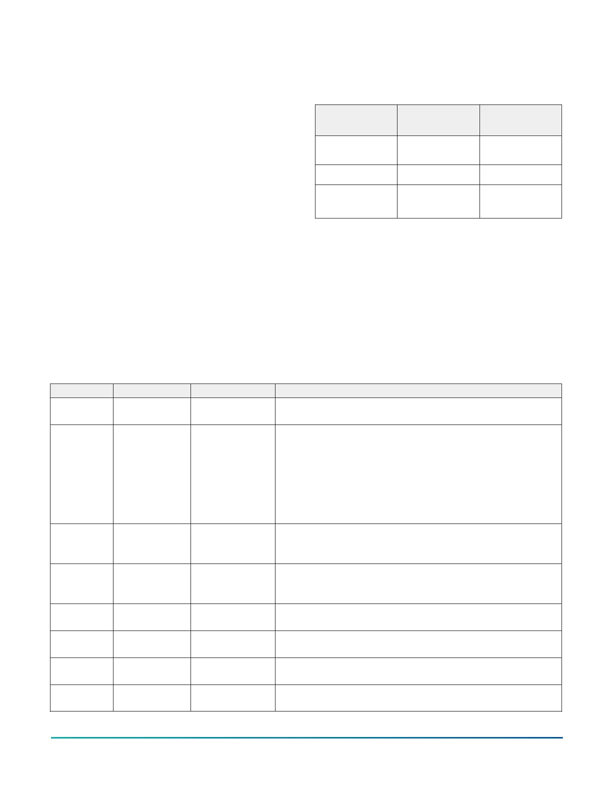
Commission controllers using the following connection
types.
Connection
Type
CGM CGE
MAP 4.2+/
BACnet Router
X X
Direct Ethernet X
Supervisor
Passthru
11
X X
1 Engines need to be at release 9.0 or later
Troubleshooting equipment
controllers
Observe the Status LEDs on the front of the equipment
controller. provides LED status indicator information
for troubleshooting the controller. To troubleshoot an
integral or local controller display, refer to the DIS1710
Local Controller Display Technical Bulletin (LIT-12011666)
or to the M4-DLK03050 Local Controller Display Technical
Bulletin (LIT-12013762).
LED status and states
Table 9: Status LEDs and description of LED states
LED label LED color Normal state Descriptions of LED states
POWER Green On Steady Off Steady = No power
On Steady = Power is supplied by primary voltage
FAULT Red Off Steady 2 blinks followed by long pause = Controller powered on in default state.
For more information about this default state, see Input/Output Wiring
Validation.
Blink - 2 Hz = Download or startup in progress, not ready for normal
operation, SA Bus devices offline (such as netsensors)
Rapid blink = SA Bus communications issue
Off Steady = No faults
On Steady = Device fault or no application loaded
FC BUS Green Blink - 2 Hz Blink - 2 Hz = Data transmission (normal communication)
Off Steady = No data transmission (auto baud in progress)
On Steady = communication lost, waiting to join communication bus
SA BUS Green Blink - 2 Hz Blink - 2 Hz = Data transmission (normal communication)
Off Steady = No data transmission (N/A - auto baud not supported)
On Steady = Communication lost; waiting to join communication bus
FC EOL (CGM
models)
Amber Off (except on
terminating devices)
On Steady = EOL is active
Off Steady = EOL is not active
ETH-1 (CGE
models)
Green Off Off Steady = ETH-1 is not connected
Blinking = ETH-1 connected and communicating
ETH-2 (CGE
models)
Green Off Off Steady = ETH-2 is not connected
Blinking = ETH-2 connected and communicating
FAULT
SA BUS
Red
Green
Both blink six times in sequence = no valid firmware on the device
( Applicable to CGE models only)
M4-CG Series General Purpose Application Controller Installation Guide20

 Loading...


