Note: For detailed information about EOL
termination rules and EOL switch settings on
FC Buses, refer to the MS/TP Communications
Bus Technical Bulletin (LIT-12011034).
3. If the controller is a terminating device on the FC
Bus, set the EOL switch to ON. If the controller is
not a terminating device on the bus, set the EOL
switch to Off.
When a controller is connected to power with its
EOL switch set to ON, the amber EOL LED on the
controller cover is illuminated.
Setting the UI current loop jumpers
CAUTION
Risk of Electric Shock:
Disconnect supply power to the devices before
attempting to adjust the UI current loop jumpers.
Failure to disconnect the supply power may result in
electric shock.
ATTENTION
Mise En Garde: Risque de décharge électrique:
Débrancher l'alimentation de l'controller avant tout
réglage du UI current loop jumpers. Le non-respect de
cette précaution risque de provoquer une décharge
électrique.
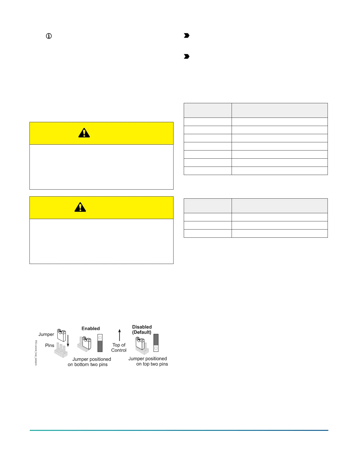
The UI current loop jumpers are on the circuit board
under the controller cover near the UI terminals (Figure
13). When a UI is defined (in the system software) as a
4-20 mA Analog Input, set the UI's current loop jumper to
the Enabled position (Figure 15).
Figure 15: UI Current Loop Jumper Positions
Setting the current loop jumper to the Enabled position,
connects an internal 100 ohm resistor across the UI
terminals, which maintains the 4-20 mA current loop
circuit even when power to the controller is interrupted or
off.
Important: Current Loop jumpers must be in the
Disabled (default) position for all UIs that are not set
up to operate as 4-20 mA analog inputs.
Important: A current loop jumper must be in the
Enabled position to maintain a closed 4-20 mA
current loop.
The following tables identify the current loop switches
associated with each UI on the CG series controllers.
Table 7: CGM09090 and CGE09090 UI Inputs and jumper
labels
Universal Input
label
Jumper label on circuit board
UI-1 J13
UI-2 J14
UI-3 J15
UI-4 J16
UI-5 J17
UI-6 J18
UI-7 J19
Table 8: CGM04060 and CGE04060 UI Inputs and jumper
labels
Universal Input
label
Jumper label on circuit board
UI-1 J10
UI-2 J11
UI-3 J12
Setting up a local display
CGM/CGE models that do not have an integral display can
be connected to an MS-DIS1710 local controller display.
Compatibility depends on the firmware version running in
the equipment controller and the display.
The DLK0350 and DIS1710 models should not be
connected to CGM/CGE -0H models that include an
integral display.
For detailed information about setting up and operating
a remotely connected DLK0350 display, refer to the
M4-DLK0350 Local Controller Display Technical Bulletin
(LIT-12013762). For detailed information about setting
up and operating a remotely connected DIS1710 display,
refer to the DIS1710 Local Controller Display Technical
Bulletin (LIT-12011270).
Input/Output Wiring Validation
The CGM/CGE controllers ship with a default state that
can assist in validating the wiring of the input and output
terminals prior to download of an application file. When
the controller is powered on in this state, the Fault LED
will flash in a pattern of two quick blinks and then a long
pause (see LED status and states).
To make use of this feature, ensure the rotary switches
are set to the desired address or controller number and
wire the input and output terminals. Apply power to the
controller and connect to the device with either a MAP
M4-CG Series General Purpose Application Controller Installation Guide 19

 Loading...


