Cable and wire length guidelines
Table 4 defines cable length guidelines for the various wire sizes that may be used for wiring low-voltage (<30 V) input
and outputs. The required wire sizes and lengths for high-voltage (>30 V) Relay Outputs are determined by the load
connected to the relay, and local, national or regional electrical codes.
Table 4: Cable length guidelines
Guideline Wire size/Gauge and type Maximum cable length
and type
Assumptions
1.0 mm (18 AWG) stranded copper 457 m (1,500 ft) twisted
wire
0.8 mm (20 AWG) stranded copper 297 m (975
ft) twisted wire
297 m (975 ft) twisted
wire
0.6 mm (22 AWG) stranded copper 183 m (600
ft) twisted wire
183 m (600 ft) twisted
wire
A
0.5mm (24 AWG) stranded copper 107 m (350 ft)
twisted wire
107 m (350 ft) twisted
wire
100 mV maximum voltage drop
Depending on the cable length and the
connected input or output device, you may
have to define an offset in the setup software
for the input or output point.
1.0 mm (18 AWG) stranded copper 229 m (750 ft) twisted
wire
0.8 mm (20 AWG) stranded copper 297 m (975
ft) twisted wire
137 m (450 ft) twisted
wire
0.6 mm (22 AWG) stranded copper 183 m (600
ft) twisted wire
91 m (300 ft) twisted wire
B
0.5 mm (24 AWG) stranded copper 107 m (350
ft) twisted wire
61 m (200 ft) twisted wire
100 mV maximum voltage drop
Depending on the cable length and the
connected input or output device, you may
have to define an offset in the setup software
for the input or output point.
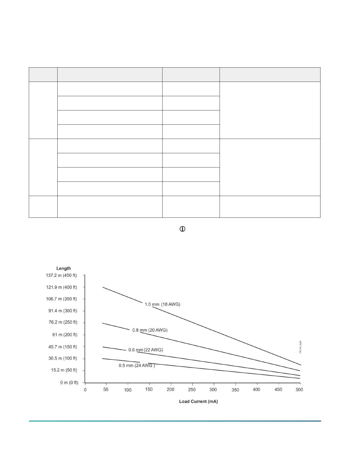
C See Figure 10 to select wire size/gauge.
Use stranded copper wire.
See Figure 10 to
determine cable length.
Use twisted wire cable.
N/A
Maximum cable length versus load current
Use the following figure to estimate the maximum cable
length relative to the wire size and the load current (in
mA) when wiring inputs and outputs.
Note: Figure 10 applies to low-voltage (<30 V) inputs
and outputs only.
Figure 10: Maximum wire length for low-voltage (<30 V) Inputs and Outputs by current and wire size
M4-CG Series General Purpose Application Controller Installation Guide 9

 Loading...


