configured for N2 network communication, you must
download and commission the controller using the SA Bus
port.
The Sensor port is connected internally to the SA
Bus terminal block. See Table 5 for more information
about communication bus port functions, ratings, and
requirements. The SA Bus port pin assignment is shown in
Figure 8.
Supply power terminal block
The 24 VAC supply power terminal block is a gray,
removable, 2-pin terminal block that fits into a board-
mounted pin header on the top right of the controller.
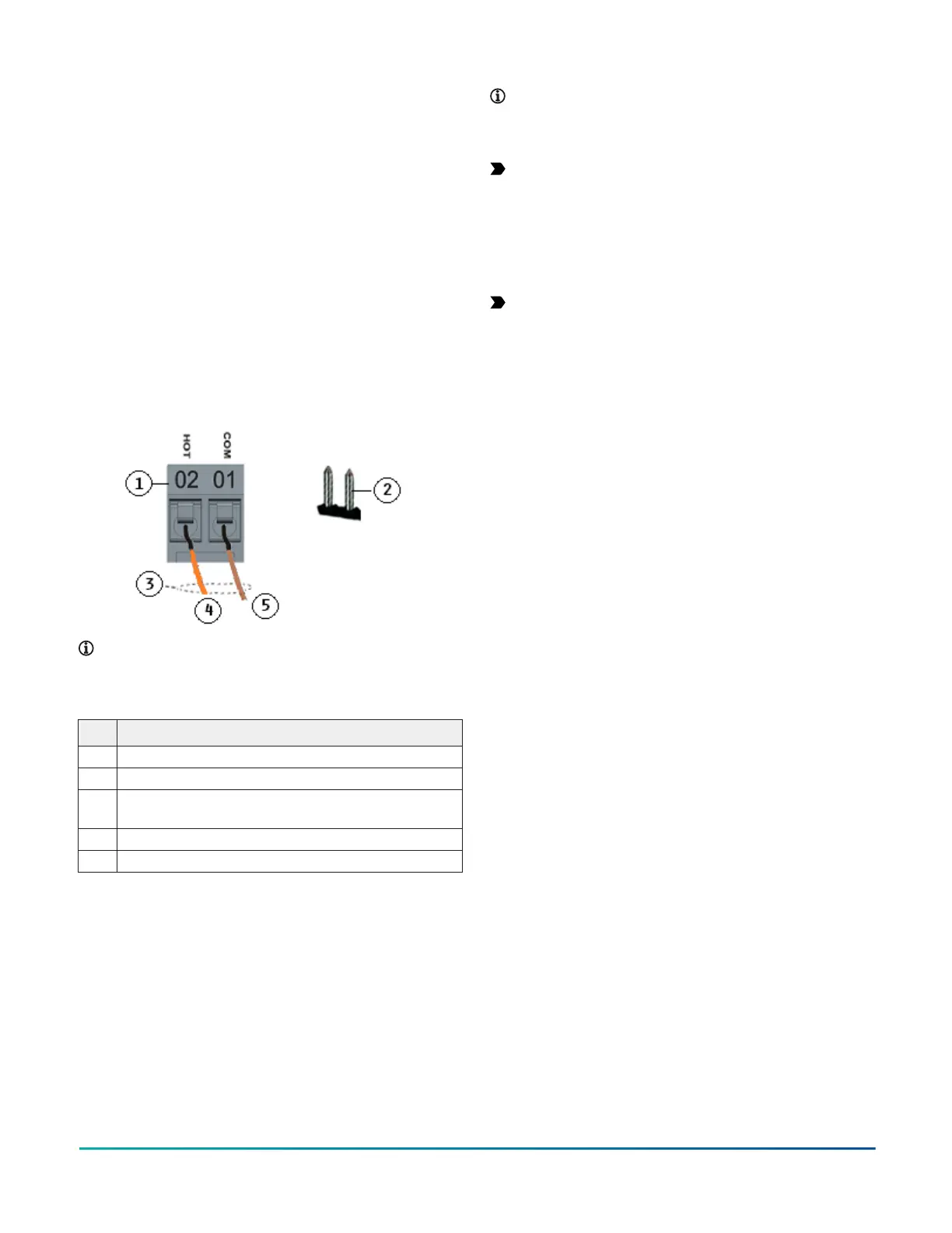
Wire the 24 VAC supply power wires from the transformer
to the HOT and COM terminals on the terminal plug as
shown in Figure 9. For more information about the Supply
Power Terminal Block, see Table 5.
Figure 9: 24 VAC supply power terminal block wiring
Note: The order of the HOT and COM terminals on
the CG series controllers is reversed from the order
of the terminals on the CV series controllers.
Table 2: Supply power terminal block wiring
Description
1 Supply power terminal block
2 Supply power terminal header
3 Wires from Johnson Controls 24 VAC, class 2 power
transformer
4 24 VAC (Orange wire)
5 COM (Brown wire)
Note: The supply power wire colors may be different
on transformers from other manufacturers. Refer to
the transformer manufacturer’s instructions and the
project installation drawings for wiring details.
Important: Connect 24 VAC supply power to the
equipment controller and all other network devices
so that transformer phasing is uniform across the
network devices. Powering network devices with
uniform 24 VAC supply power phasing reduces
noise, interference, and ground loop problems. The
equipment controller does not require an earth
ground connection.
Important: Power wires must be less than 30
meters (100 ft) between controller and transformer
Terminal wiring guidelines, functions,
ratings, and requirements
This section provides further guidelines on input and
output wiring, maximum cable length versus load current,
and SA Bus and supply power wiring.
For information about removing a terminal block from the
controller, see Removing a terminal block.
Input and Output wiring guidelines
Table 3 provides information and guidelines about the
functions, ratings, and requirements for the controller
input and output terminals, and Table 3 also references
guidelines for determining proper wire sizes and cable
lengths.
In addition to the wiring guidelines in Table 3, observe the
following guidelines when wiring controller inputs and
outputs:
• Run all low-voltage wiring and cables separate from
high-voltage wiring.
• All input and output cables, regardless of wire size or
number of wires, must consist of twisted, insulated,
and stranded copper wires.
• Shielded cable is not required for input or output
cables but is recommended for input and output cables
that are exposed to high electromagnetic or radio
frequency noise.
• Cable runs of less than 30 m (100 ft) often do not
require an offset in the input/output software setup.
• Cable runs over 30 m (100 ft) often require an offset in
the input/output software setup.
M4-CG Series General Purpose Application Controller Installation Guide6

 Loading...


