Configuring wireless communications
(CGM models only)
To configure a CGM controller for use with the ZFR Pro
Series Wireless Field Bus system, complete the following
steps:
1. Disconnect the 24 VAC supply from the controller.
2. Wire the input/output terminals and SA Bus.
Note: In wireless network applications, do
not connect any wires to the FC Bus terminal
block. (Connect the SA/FC terminal block on
expansion modules to an SA Bus only.)
3. Important: Before the CGM controller is powered
on, connect the /ZFR Pro Wireless Field Bus Router
to the FC Bus port (RJ-12 modular jack) on the front
of the controller.
4. Ensure that the controller's rotary switches are
set to the correct device address. For details about
setting a device address, see Setting the device
address on CGM models.
5. Reconnect the 24 VAC supply to the controller.
For more information about the ZFR Pro Wireless
Field Bus system, refer to the WRG1830/FX-ZFR183x
Pro Series Wireless Field Bus System Technical Bulletin
(LIT-12013553).
Setting the device address on CGM
models
Metasys equipment controllers are master devices on MS/
TP (FC or SA) Buses. Before you operate controllers on a
bus, you must set a valid and unique device address for
each controller on the bus.
The following table describes the valid rotary switch
device addresses for communications bus applications.
FC Bus communication
mode
Valid device address range
Wired MS/TP
communication
4-127
Note: Addresses 0-3 are
reserved and not for use on
equipment controllers.
Zigbee wireless
communication
4-127
Note: Addresses 0-3 are
reserved and not for use on
equipment controllers.
N2 communication 1-254
Note: Addresses 0 and 255 are
reserved and not for use on
equipment controllers.
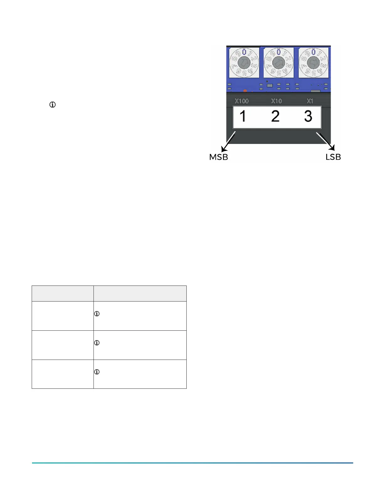
The device address is a decimal address set using three
rotary switches located at the top of the controller. The
numbers are ordered from left to right, most significant
bit (MSB) to least significant bit (LSB) when the controller
is oriented as shown in Figure 1. In the following figure,
the switches are set to 1 2 3, designating this controller's
device address as 123.
Figure 11: Rotary switch block
The device address must match the device address
defined in the Controller Configuration Tool (CCT) under
Define Hardware > Network Settings.
To set the device addresses on controllers, complete the
following steps:
1. Set a unique and sequential device address for each
of the devices connected on the FC or SA, starting
with device address 4.
2. To ensure the best bus performance, set sequential
device addresses with no gaps in the device address
range (4, 5, 6, 7, 8, 9, and so on). The devices do not
need to be physically connected on the bus in their
numerical device address order.
3. Write each controller's device address on the white
label below the Device Address Rotary Switch Block
on the controller's cover.
For more information about controller device addresses
and how to set them on MS/TP buses, refer to the MS/TP
Communications Bus Technical Bulletin (LIT-12011034).
Setting the controller number for CGE
models
The rotary switches on the CGE models are used to set
the controller number. The controller number can be
utilized to physically identify the controller and relate
it to the building drawings. The factory default BACnet
device ID is calculated from the value of the controller
number added to 2000000. Each equipment controller on
a BACnet/IP network must have a unique BACnet device
ID on the subnet where it resides in order for proper
identification and communication. To ensure a unique
value, the BACnet device ID should be configured in CCT
instead of relying on this default calculation. This step
will be necessary on sites with more than 1000 devices as
controller numbers will be duplicated.
The controller number is set using three rotary switches
and may be numbered from 000 to 999. The numbers are
ordered from left to right, most significant bit (MSB) to
least significant bit (LSB).
In Figure 11, the switches are set to 1 2 3, designating
this controller as controller number 123. The controller
M4-CG Series General Purpose Application Controller Installation Guide 17

 Loading...


