349218-JIM-F-0512
Johnson Controls Unitary Products 15
Thermostat Wiring
The thermostat should be located on an inside wall approximately
56 inch above the floor where it will not be subject to drafts, sun
exposure or heat from electrical fixtures or appliances. Follow the
manufacturer's instructions enclosed with thermostat for general
installation procedure. Seven (7) color-coded, insulated wires
should be used to connect the thermostat to the unit. Refer to
Table 7 for control wire sizing and maximum length.
Space Sensor
The space sensor, if used, should be located on an inside wall
approximately 56 inches above the floor where it will not be
subject to drafts, sun exposure or heat from electrical fixtures or
appliances. Follow manufacturer's instructions enclosed with
sensor for general installation procedure.
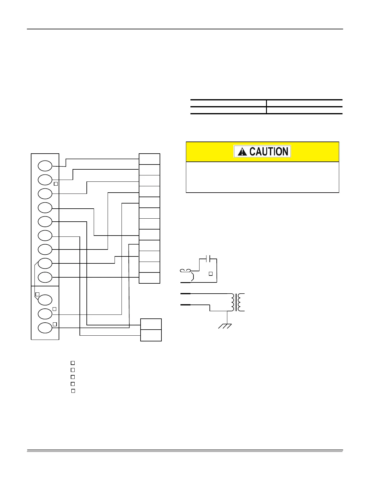
Figure 12: Typical Field Wiring 24 Volt Thermostat
Table 7: Control Wire Sizes
Wire Size Maximum Length
1
1. From the unit to the thermostat and back to the unit.
18 AWG 150 Feet
OCC
C
RC
G
Y2
Y1
W2
W1
X
R
THERMOSTAT
TERMINALS
CONTROL
TERMINAL
BLOCK
TERMINALS ON
A LIMITED
NUMBER OF
THERMOSTATS
1
4
3
1
2
4
Second stage heating not required on single stage heating units.
Jumper is required if there is no Smoke Detector circuit.
Jumper is required for any combination of R, RC, or RH.
5
5
OCC is an output from the thermostat to indicate the Occupied condition.
X is an input to the thermostat to display Error Status conditions.
Y3
Y4
3
W2
Y1
G
OCC
P
P1
Y2
X
R
SD
C
EXPANSION
BOARD
TERMINAL
BLOCK
W1
Y3
Y4
2
C
SD
SD
R
Jumper
Smoke
Detector
24 VAC
Class 2
208/230-3-60 and 380/415-3-50 units control
transformers are factory wired for 230v and 415v power
supply respectively. Change tap on transformer for 208-
3-60 or 380-3-50 operation. See unit wiring diagram.

 Loading...