349218-JIM-F-0512
Johnson Controls Unitary Products 43
Air Balance
Start the supply air blower motor. Adjust the resistances in both
the supply and the return air duct systems to balance the air
distribution throughout the conditioned space. The job
specifications may require that this balancing be done by
someone other than the equipment installer.
To check the supply air CFM after the initial balancing has been
completed:
1. Remove the two 5/16” dot plugs from the blower motor and
the filter access panels shown in the Unit Dimensions and
Rear View Clearances Figure 6.
2. Insert at least 8" of 1/4 inch tubing into each of these holes
for sufficient penetration into the air flow on both sides of
the indoor coil.
NOTE: The tubes must be inserted and held in a position
perpendicular to the air flow so that velocity pressure
will not affect the static pressure readings.
3. Using an inclined manometer, determine the pressure drop
across a dry evaporator coil. Since the moisture on an
evaporator coil may vary greatly, measuring the pressure
drop across a wet coil under field conditions would be
inaccurate. To assure a dry coil, the compressors should
be deactivated while the test is being run.
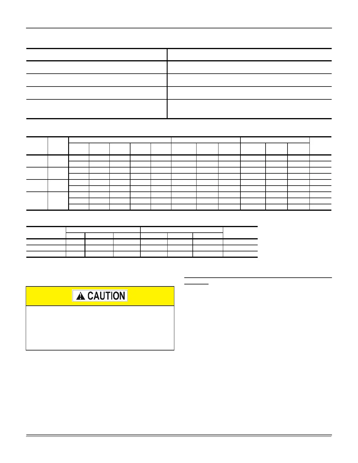
Table 17: RPM Selection
Size
(Tons)
Model HP
Max
BHP
Motor
Sheave
Blower
Sheave
6 Turns
Open
5 Turns
Open
4 Turns
Open
3 Turns
Open
2 Turns
Open
1 Turn
Open
Fully
Closed
J15
(15)
ZJ
5 5.75 1VP65 BK110 815 850 885 920 950 985 N/A
5 5.75 1VP65 BK090 1010 1055 1095 1135 1180 1220 N/A
J18
(17.5)
ZJ
5 5.75 1VP60 BK110 730 765 800 835 870 905 N/A
7.5 8.63 1VP60 BK090 905 950 990 1035 1075 1120 N/A
J20
(20)
ZJ
5 5.75 1VP60 BK110 730 765 800 835 870 905 N/A
7.5 8.63 1VP60 BK090 905 950 990 1035 1075 1120 N/A
J25
(25)
ZJ
7.5 8.63 1VP60 1B5V94 810 850 885 920 960 1000 N/A
10 11.50 1VP75X 1B5V110 975 1005 1040 1070 1100 1135 1165
15 17.25 1VP75X 1B5V94 1140 1180 1215 1255 1290 1330 1365
Table 18: Indoor Blower Specifications
Size
(Tons)
Model
Motor Motor Sheave Blower Sheave
Belt
HP RPM Eff. SF Frame
Datum Dia.
(in.)
Bore (in.) Model
Datum Dia.
(in.)
Bore (in.) Model
J15
(15)
ZJ
5 1725 0.89 1.15 184T 5.2 - 6.4 1 1/8 1VP65 10.4 1 BK110 BX83
5 1725 0.89 1.15 184T 5.2 - 6.4 1 1/8 1VP65 8.4 1 BK090 BX81
J18
(17.5)
ZJ
5 1725 0.89 1.15 184T 4.2 - 5.5 1 1/8 1VP60 10.4 1 3/16 BK110 BX78
7.5 1725 0.91 1.15 213T 4.2 - 5.5 1 3/8 1VP60 8.4 1 3/16 BK090 BX75
J20
(20)
ZJ
5 1725 0.89 1.15 184T 4.2 - 5.5 1 1/8 1VP60 10.4 1 3/16 BK110 BX78
7.5 1725 0.91 1.15 213T 4.2 - 5.5 1 3/8 1VP60 8.4 1 3/16 BK090 BX75
J25
(25)
ZJ
7.5 1725 0.91 1.15 213T 4.2 - 5.5 1 3/8 1VP60 9.5 1 7/16 1B5V94 BX78
10 1725 0.89 1.15 215T 5.8 - 7.0 1 3/8 1VP75X 11.1 1 7/16 1B5V110 5VX840
15 1725 0.91 1.15 254T 6.2 - 7.4 1 5/8 1VP75X 9.5 1 7/16 1B5V94 5VX860
Table 19: Power Exhaust Specifications
Voltage
Motor Motor
CFM @
0.1 ESP
HP RPM
1
1. Motors are multi-tapped and factory wired for high speed.
QTY LRA FLA MCA
208/230-1-60 3/4 1075 1 7.7 5.0 6.25 5250
460-1-60 3/4 1075 1 4.1 2.2 2.75 5250
575-1-60 3/4 1050 1 2.84 1.5 1.875 5250
On VAV units be certain that the VFD drive is set to
maximum output, exhaust dampers are closed and
individual space damper boxes are full open.
VFD units with bypass must not be in bypass mode
(‘LINE’ position) unless all individual space dampers are
full open.

 Loading...