349218-JIM-F-0512
Johnson Controls Unitary Products 9
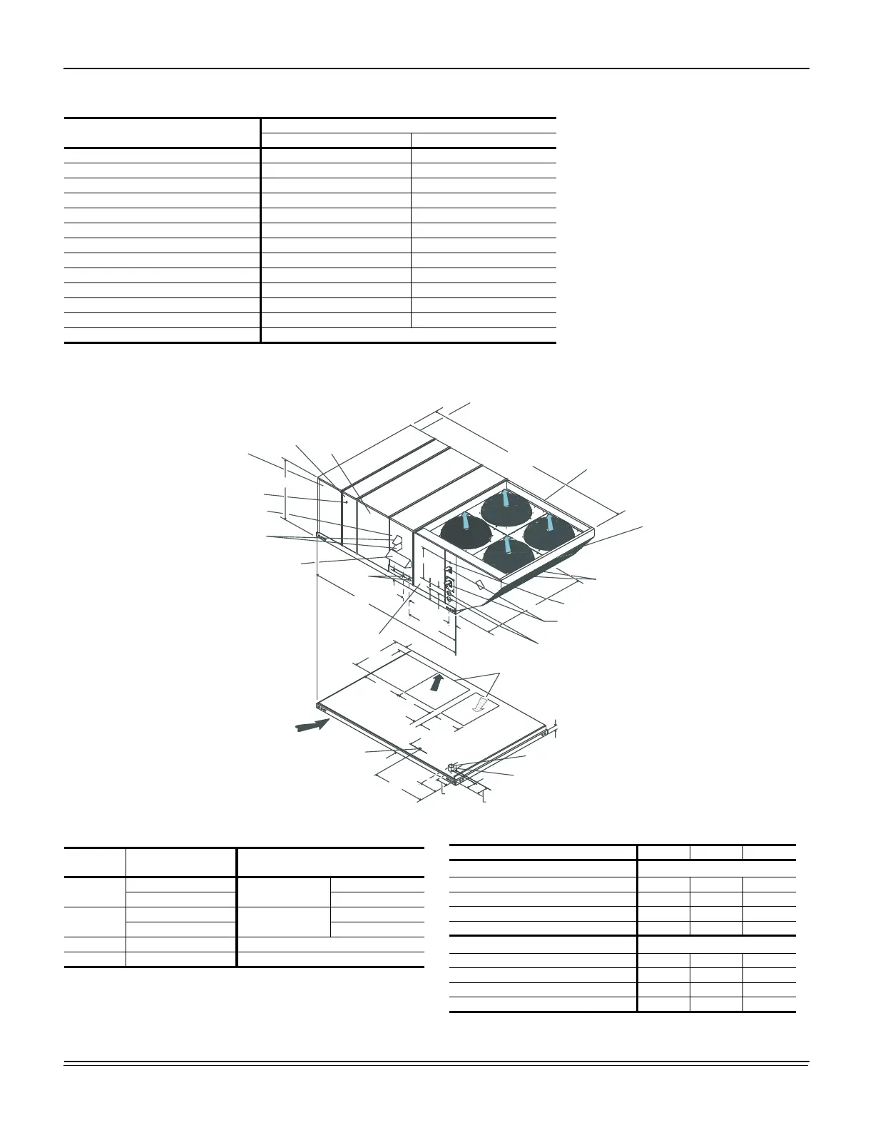
Figure 5: J15 thru 25 ZJ Unit Dimensions Front View
Note: All entry holes should be sealed to prevent rain water entry
into building.
Table 3: J15 thru 25 ZJ Unit Accessory Weights
Unit Accessory
Weight (lbs.)
Shipping Operating
Economizer 165 160
Power Exhaust 90 85
Electric Heat
1
40 40
Gas Heat
2
240 240
Double Wall 260 260
Motorized Damper 150 150
Barometric Damper 50 45
Econ./Motorized Damper Rain Hood 60 55
Econ./Power Exhaust Rain Hood 95 90
Wood Skid 220 220
Roof Curb 190 185
Hot Gas Bypass 10 10
Supply Fan VFD See Table 5
1. Weight given is for the maximum heater size available (54KW).
2. Weight given is for the maximum number of tube heat exchangers available (8 tube).
11-1/2
(A) CONTROL WIRING
ENTRY
COIL
GUARD
KIT
CONDENSER
COILS
(B) POWER
WIRING
ENTRY
5
9-3/4
21.00
6-3/8
7-1/8
35
5-7/8
136-1/4
GAS OR ELECTRIC
HEAT
ACCESS
DOT PLUG
(For pressure
drop reading)
BLOWER
COMPARTMENT
ACCESS
(Auxiliary)
(C) GAS
SUPPLY
ENTRY
CONTROL BOX
ACCESS
VENT AIR
OUTLET
HOODS
BLOWER MOTOR
ACCESS (Location
of Optional VFD Bypass)
BLOWER ACCESS
(Location of
Optional VFD)
52-5/8
180-19/32
COMPRESSOR ACCESS
DISCONNECT
SWITCH
LOCATION
ECONOMIZER / MOTORIZED DAMPER
FIXED OUTDOOR INTAKE AIR AND
POWER EXHAUST RAIN HOODS
(See detail Y)
92
46-5/8
35-1/4
33
2-3/4
3-3/4
(B) POWER WIRING
ENTRY
BOTTOM SUPPLY
AND RETURN
AIR OPENINGS
(See Note)
(A) CONTROL WIRING
ENTRY
21-1/2
11-1/8
(D)
GAS SUPPLY
ENTRY
UNIT BASE RAILS
Shown separately to illustrate
RETURN
AIR
Bottom Duct openings. Power
and Gas Piping Connection
location.
NOTE:
For curb mounted units, refer to the curb hanger
dimensions of the curb for proper size of the
supply and return air duct connections.
12-1/2
9-1/4
8-1/8
46-5/8
9-3/4
COMBUSTION
AIR INLET HOOD
SUPPLY
AIR
Table 4: Utilities Entry
Hole
Opening Size
Diameter
Used For
A
1-1/8” KO
Control Wiring
Front
3/4” NPS (Fem.) Bottom
B
3-5/8” KO
Power Wiring
Front
3” NPS (Fem.) Bottom
C 2-3/8” KO Gas Piping (Front)
1
1. One-inch Gas Piping NPT Required.
D 1-11/16” Hole Gas Piping (Bottom)
1,2
2. Opening in the bottom to the unit can be located by the slice in the
insulation.
Table 5: Supply Fan VFD Weights, In Lbs.
Supply Fan Motor 230V 460V 575V
W/O Manual Bypass
5.0 hp
25 25 30
7.5 hp
30 30 30
10.0 hp
30 30 35
15.0 hp
30 30 40
W/Manual Bypass
5.0 hp
30 30 35
7.5 hp
35 35 35
10.0 hp
35 35 40
15.0 hp
40 35 45

 Loading...