349218-JIM-F-0512
Johnson Controls Unitary Products 53
Checking Gas Heat Input
1. Turn off all other gas appliances connected to the gas meter.
2. With the furnace turned on, measure the time needed for
one revolution of the hand on the smallest dial on the
meter. A typical gas meter usually has a 1/2 or a 1 cubic
foot test dial.
3. Using the number of seconds for each revolution and the
size of the test dial increment, find the cubic feet of gas
consumed per hour from the Gas Rate - Cubic Feet Per
Hour Table 24.
If the actual input is not within 5% of the furnace rating (with
allowance being made for the permissible range of the regulator
setting), replace the orifice spuds with spuds of the proper size.
NOTE: To find the Btu input, multiply the number of cubic feet
of gas consumed per hour by the Btu content of the gas
in your particular locality (contact your gas company for
this information - it varies widely from city to city.).
EXAMPLE
By actual measurement, it takes 13 seconds for the hand on the
1-cubic foot dial to make a revolution with just a 300,000 Btuh
furnace running. Read across to the column in the table above,
headed “1 Cubic Foot”, where you will see that 278 cubic feet of
gas per hour are consumed by the furnace at that rate. Multiply
278 x 1050 (the Btu rating of the gas obtained from the local
gas company). The result is 292,425 Btuh, which is close to the
300,000 Btuh rating of the furnace.
Manifold Gas Pressure Adjustment
Small adjustments to the high-fire gas flow may be made by
turning the pressure regulator adjusting screw on the automatic
gas valve.
Adjust as follows:
1. Remove the cap on the regulator. It's located next to the
push-on electrical terminals.
2. To decrease the gas pressure, turn the adjusting screw
counterclockwise.
3. To increase the gas pressure, turn the adjusting screw
clockwise.
NOTE: The correct manifold pressure for these furnaces is
3.65 IWG ± 0.3.
Adjustment Of Temperature Rise
The temperature rise (the difference of temperature between the
return air and the heated air from the furnace) must lie within the
range shown on the CSA rating plate and the data in Table 11.
After the temperature rise has been determined, the CFM can
be calculated as follows:
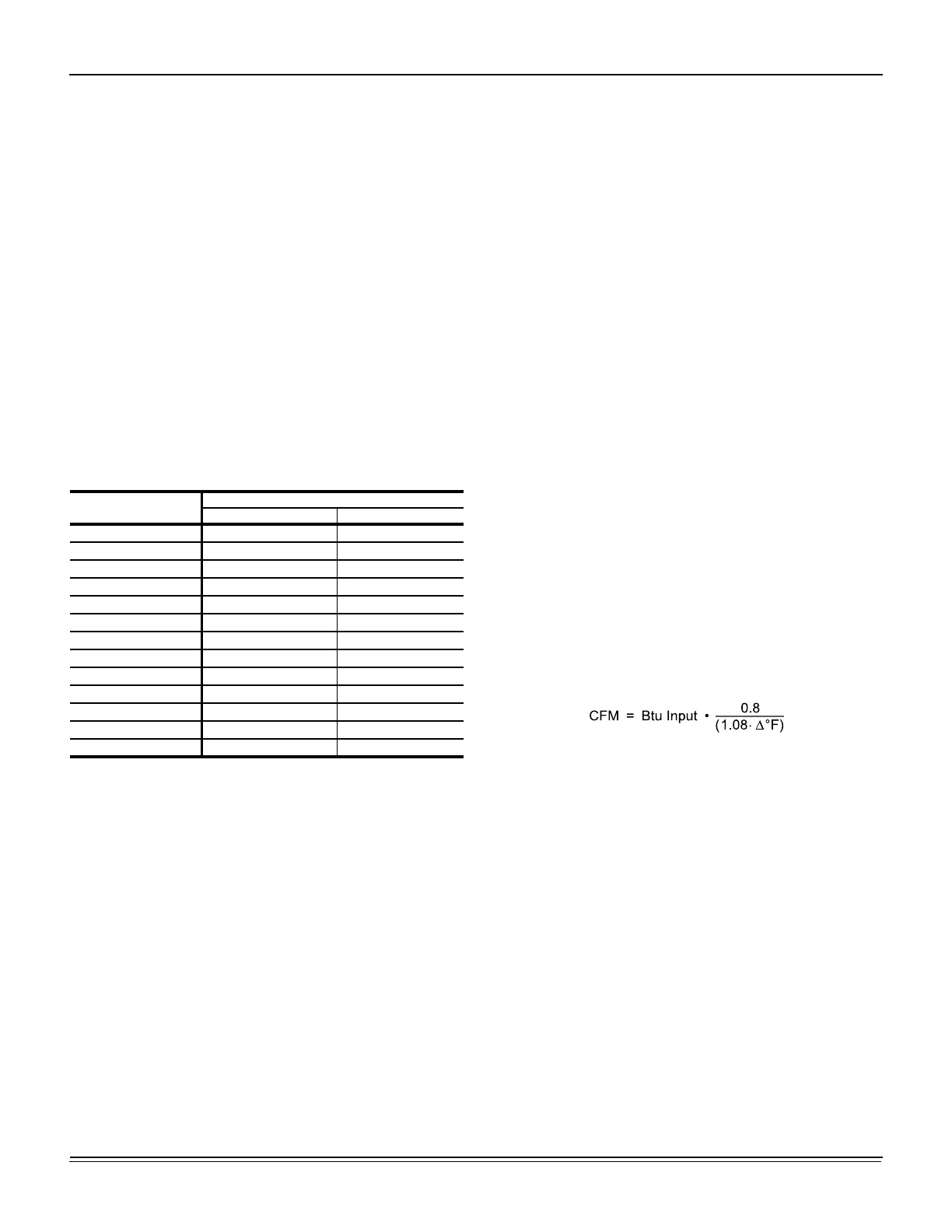
Table 24: Gas Rate Cubic Feet Per Hour
Seconds for
One Rev.
Size of Test Dial
1/2 cu. ft. 1 cu. ft.
4 450 900
6 300 600
8 228 450
10 180 360
12 150 300
14 129 257
16 113 225
18 100 200
20 90 180
22 82 164
24 75 150
26 69 138
28 64 129

 Loading...