349218-JIM-F-0512
Johnson Controls Unitary Products 17
J25
(25)
208-3-60 23.0 160 31.5 3.7 28.0 0.0
None - - - 141.8 150
E18 13.5 1 37.5 141.8 150
E36 27.0 2 74.9 141.8 150
E54 40.6 2 112.7 175.9 200
E72 54.1 2 150.2 185.2 200
230-3-60 23.0 160 31.5 3.7 26.0 0.0
None - - - 139.3 150
E18 18.0 1 43.3 139.3 150
E36 36.0 2 86.6 140.8 150
E54 54.0 2 129.9 162.4 175
E72 72.0 2 173.2 205.7 225
460-3-60 12.2 87 17.1 1.9 13.0 0.0
None - - - 72.7 80
E18 18.0 1 21.7 72.7 80
E36 36.0 2 43.3 72.7 80
E54 54.0 2 65.0 81.2 90
E72 72.0 2 86.6 102.9 110
575-3-60 8.7 62 13.5 1.5 10.3 0.0
None - - - 53.7 60
E18 18.0 1 17.3 53.7 60
E36 36.0 2 34.6 56.2 60
E54 54.0 2 52.0 64.8 70
E72 72.0 2 69.3 82.2 90
1. Minimum Circuit Ampacity.
2. Dual Element, Time Delay Type.
3. HACR type per NEC.
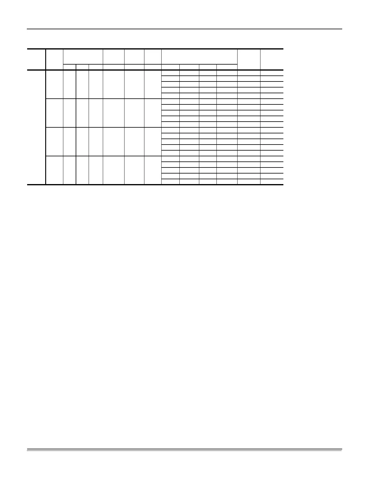
J15 thru 25 ZJ - Standard Drive Without Powered Convenience Outlet (Continued)
Size
(Tons)
Volt
Compressors
(each)
OD Fan
Motors
(each)
Supply
Blower
Motor
Pwr
Conv
Outlet
Electric Heat Option
MCA
1
(Amps)
Max Fuse
2
/
Breaker
3
Size
(Amps)
RLA LRA MCC FLA FLA FLA Model kW Stages Amps

 Loading...