542933-UIM-D-0513
10 Johnson Controls Unitary Products
4. Wire nut thermostat wire (from the indoor control) to the communication harness wires.
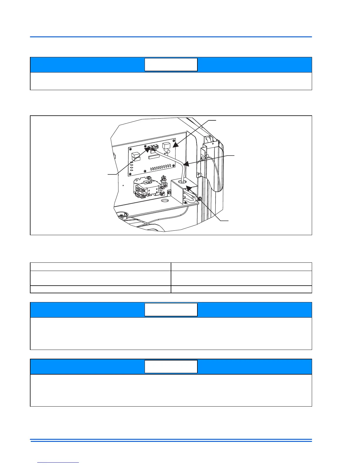
5. Set the wires which are now connected (with wire nuts) into the Junction Box of the control
housing (pictured below).
6. Set the appropriate jumper settings to insure proper control functionality (See table below).
When connecting the loose ends of the wire harness, be sure to note color for each of the four
wires (A+, R, C, B-).
FIGURE 9:
Outdoor Control Housing
Unit Control
Jumpers which must be set
Heat Pump
Fossil Fuel
Hot Heat Pump
Air Conditioner No Jumpers to set
Jumpers listed here are required and if set incorrectly will flag an error upon installation. While the
other jumpers can be set from the Touch Screen Communicating Control, it is good practice to ini-
tially set all jumpers at the respective control. This will avoid any confusion that may occur with
future service at the units.
For installation of a non-communicating outdoor unit with the Touch Screen Communicating Con-
trol, the installer should reference the indoor and outdoor unit installation instructions. If informa-
tion is not provided, there may be a need for a Communicating Interface Control Field Kit (S1-
33102953000).

 Loading...