542933-UIM-D-0513
12 Johnson Controls Unitary Products
1. Disconnect all power from system (including high and low voltage).
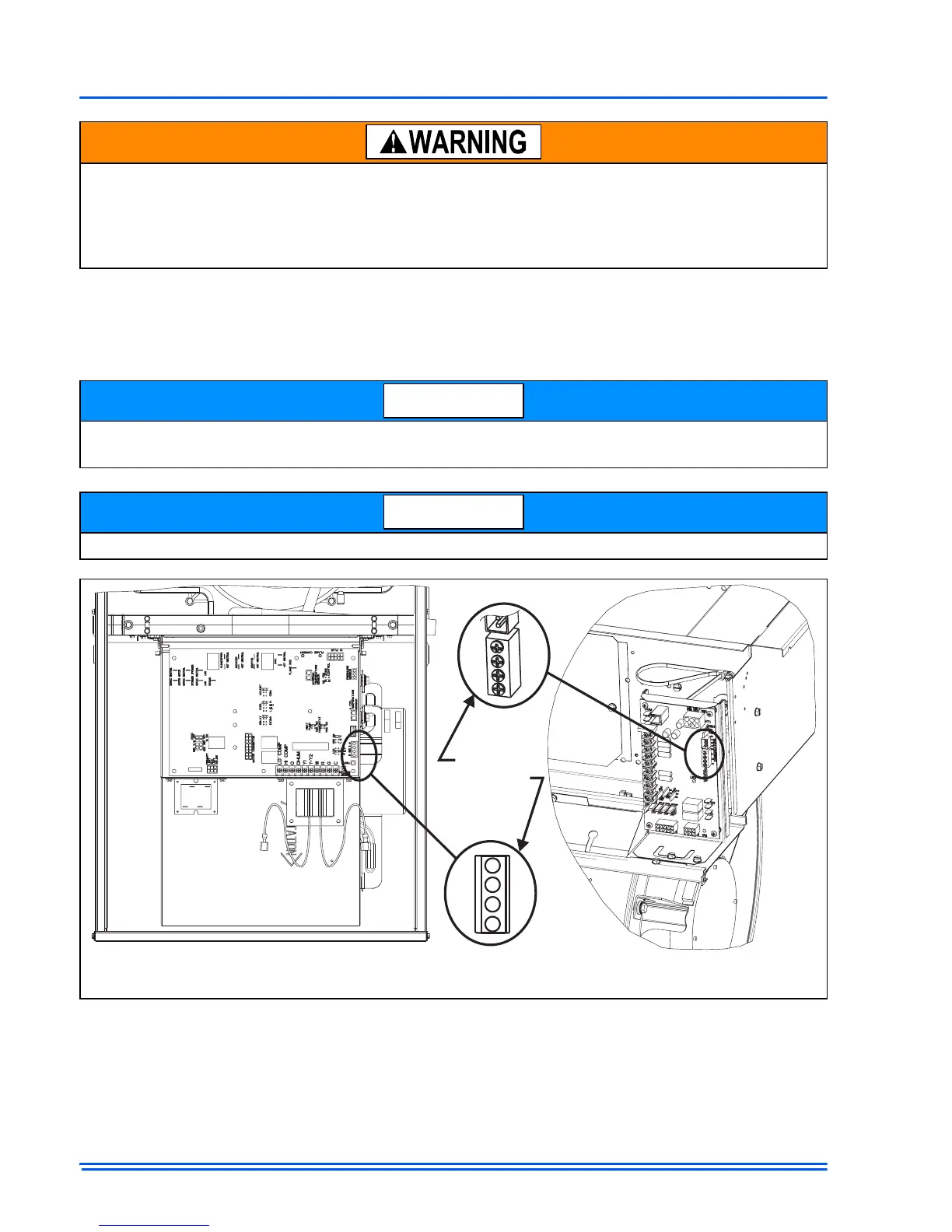
2. Screw the 4 wires from the Touch Screen Communicating Control and outdoor control to the
communicating screw terminal (8 wires in all). Be sure that all wires are connected respectively
(A+ = A+, R = R, C = C, B- = B-).
ELECTRICAL OPERATION HAZARD
Failure to follow this warning could result in personal injury, death, or equipment damage.
Before installing, modifying, or servicing system, the main electrical disconnect switch must be in
the OFF position. There may be more than 1 disconnect switch. Lock out and tag switch with a
suitable warning label.
If the installer finds that the indoor control screw terminals are presenting a challenge, wire nuts
can be used to connect the controls on the outside of the indoor unit.
The furnace control may be labeled so that C = GND.
FIGURE 11:
Indoor Screw Terminal Location

 Loading...