Installation, Operation and Maintenance Manual
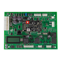
Power Status LED
Ensure SE-ZEC Controller is receiving power. A green LED shows the power supply status to the SE-ZEC Controller.
LED OFF = No Power. LED ON = Power is supplied by primary voltage (normal operation)
Communication Bus Problems
Several factors may influence the behavior of the FC Communication Bus.
I/O Wiring
The SE-ZEC Controller must be wired properly. If the SE-ZEC Controller is wired incorrectly, communication problems
may occur. These problems include devices going online and offline, or devices not coming online at all.
Duplicate Addresses
Two or more devices on a communication Bus cannot have the same address. Two controllers on the FC Communication
Bus cannot both have an address of 18, for example. If two devices on the same Bus have the same address,
performance can degrade or serious communication problems may occur. These problems include the devices not
coming online and all communication stopping completely.
Check for duplicate addresses in the following ways:
• If a specific device is not communicating, remove the device with communication problems and check if devic
e
addr
ess remains online at the MAP Gateway to determine if the device address remains online.
• If the Bus communication problems are severe and no communication is present, or you cannot determine wher
e
communication is unreliable, partition (disconnect and isolate a portion of the Bus for testing purposes) and test
the Bus portion connected to the Zone Coordinator.
Correcting Physical Communication Bus Problems
The communication Bus is subject to a number of physical factors that can affect performance. Consider the following list
of common physical problems that affect the communications Bus:
• Check status LED to verify power at the controller
• Check wires
o Verify that the wire is a 0.6 mm (22 AWG) three-conductor, twisted, shielded cable.
o Ensure the wires are not broken or frayed. Check wire connections.
Parts and Accessories
Table 8: SE-ZEC Controller Parts and Accessories
SE-ZEC500-1 Standalone Controller (Un-programmed)
SE-ZEC510-1 BACnet Controller (Un-programmed)
TE-631GV-2 Supply Air or Discharge Air Temperature Sensor
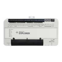
TL-MAP1810-0P Mobile Access Portal Gateway
NS-ATV7003-0 VAV Handheld Balancing Tool
NSB8BTN241-0 Network Sensor (LCD Display)
NSB8BTN141-0 Network Sensor (Warmer/Cooler Interface)
NSB8BTN041-0 Network Sensor (No Display)
 Loading...