Installation, Operation and Maintenance Manual
address range (4, 5, 6, and so on). The field controllers do not need to be physically connected on the Bus in their
numerical device address order.
4. Write each field controller’s device address on the white label below the DIP switch block on the controller’s cover.
End-of-line (EOL) Switch
The EOL switch must be set to ON for the two devices located at either end of each bus segment on an FC bus. The EOL
switches must be set to OFF for all other devices on the bus segment on an FC bus.
Optional Components
Sensor Actuator (SA) Bus
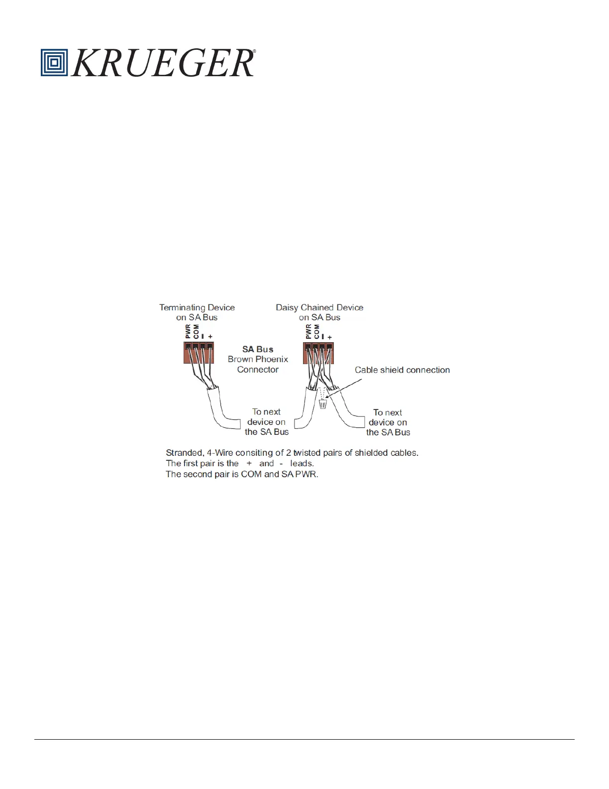
Factory or field supplied zone sensors are wired to the SA bus on the SE-ZEC Controller. The SA Bus is a brown,
removable 4-terminal plug that is keyed to only fit into the board mounted SA bus. Wire the removable SA bus terminal
block plugs on the SE-ZEC Controller and other field devices in a daisy-chain configuration using 4-wire, shielded cable.
Fig. 4: SA Bus Connections
Supply Air Temp. Sensor
Factory or field-supplied supply air temperature sensors can be used to measure the supply air temperature at the inlet of
the VAV box. The supply air temperature is wired between terminals ICOM3 and IN3 on the SE-ZEC Controller. The
sensor should be mounted in the inlet duct centered in the side of the ductwork. Avoid installing the sensor near an elbow,
take off or transition. Avoid blocking air to the primary airflow sensor.
Factory provided nickel (1k ohm) temperature sensors have 4” long probes and stainless steel mounting flanges with (2)
provided hex-head self-drilling mounting screws. Sensors come equipped with 10 ft. plenum rated cables with ¼” internal
thread insulated quick-connect terminations on leads. Install sensor by drilling a hole into the ductwork, inserting the
sensor, and securing with provided screws. The sensor tip should not touch any part of the ductwork.
With the supply air temperature sensor installed, the SE-ZEC controller will change its control sequence based on the
measured supply air temperature. When parameter Heating Limit Enable is TRUE the controller will not allow re-heat to
engage when the supply air temperature is greater than the value set in Heating Supply Air Limit.
Additionally, the controller will switch to warmup mode when warmup conditions are present. Warmup conditions are
present when the supply air temperature (SAT) sensor value exceeds the zone temperature (ZNT) sensor in unoccupied
mode or exceeds it by the Warmup Differential in occupied mode. While in Warmup mode the minimum flow will be set to
the Warmup Min Flow.
 Loading...