System 450™ Series Control Module with Ethernet Communications Installation Instructions
2
Installation
Location Considerations
Observe the following System 450 location guidelines:
• Ensure that the mounting surface can support the module assembly, mounting hardware, and any (user-
supplied) panel or enclosure.
• Mount the modules upright and plugged together in a horizontal row where possible (Figure 3). DIN rail
mounting is highly recommended.
• Mount modules on hard, even surfaces.
• Allow sufficient space for wires and connections.
• Mount the modules in locations free of corrosive vapors and observe the ambient operating conditions listed in
the Technical Specifications
.
• Do not mount the modules on surfaces that are prone to vibration or in locations where radio frequency or
electromagnetic emissions may cause interference.
• Do not install the modules in airtight enclosures.
Do not install the modules in an enclosure with heat-generating devices that may cause the
temperature to exceed the ambient operating limit.
Mounting
You can mount System 450 modules on 35 mm DIN rail (recommended) or directly to an even wall surface.
To mount modules on DIN rail:
1. Provide a section of 35 mm DIN rail that is longer than the module assembly width, and mount the DIN rail
horizontally in a suitable location using the appropriate mounting hardware.
2. Clip the control module on the rail, position the upper DIN rail clips on the top rail, and gently snap the lower
clips onto the rail.
3. Clip the remaining modules to the right of the control module onto the DIN rail, and plug the 6-pin module
connectors together (Figure 3).
63
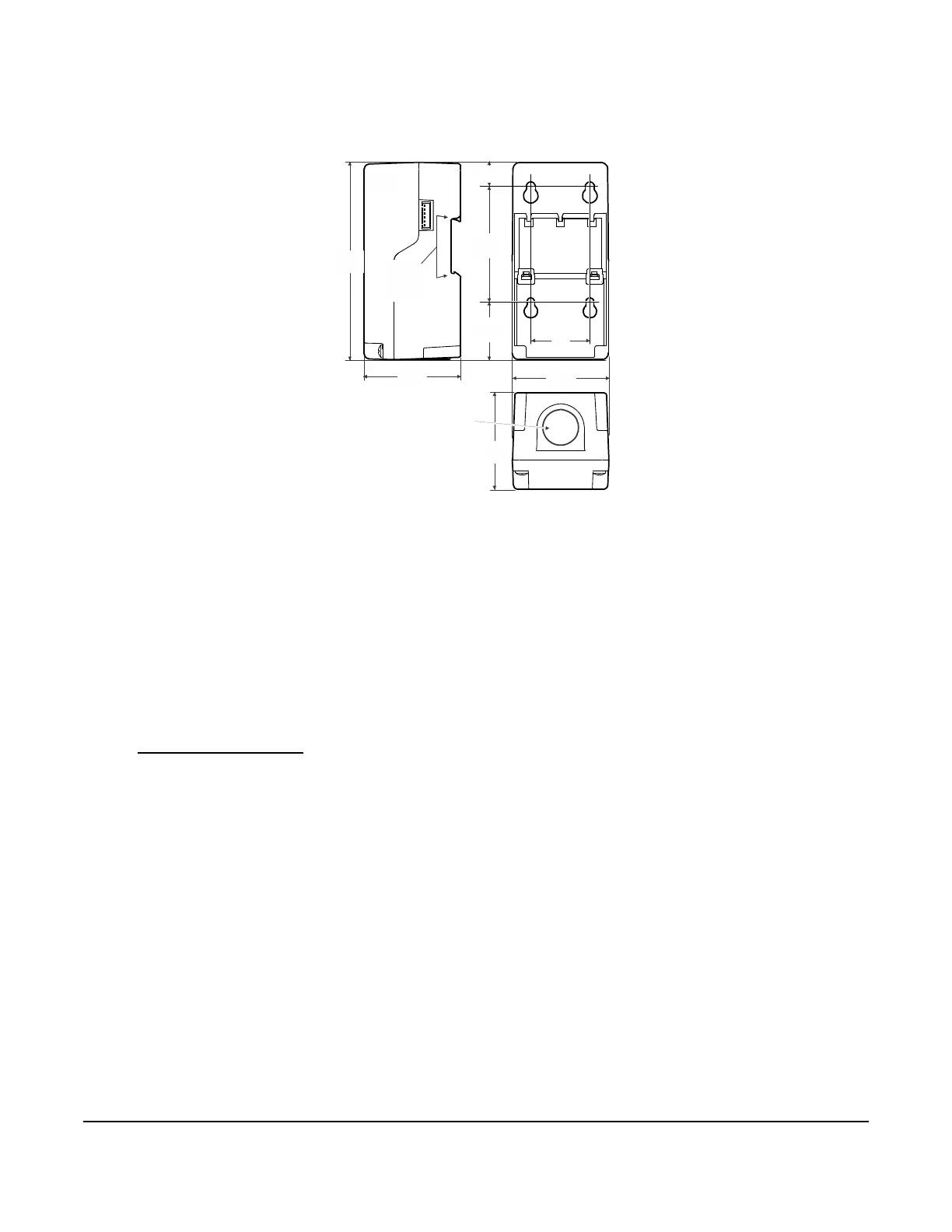
(2-1/2)
FIG:new_enclosure_dims
1/2 in. Conduit Hole
(Nominal Trade Size)
35 mm
DIN Rail
Mount
Channel
63
(2-1/2)
63
(2-1/2)
40
(1-9/16)
40
(1-9/16)
(2-15/16)
Figure 1: System 450 Module
Dimensions, mm (in.)