System 450™ Series Control Module with Ethernet Communications Installation Instructions
25
Viewing Network Settings, Setting the Remote Network UI Access Lock, and Resetting the
Network Settings
In the Communications View and Setup Start screens, you can set up the Ethernet communications parameters for
the System 450 control module. You must use a web browser on a computer that is connected to the control
module.
Refer to the System 450 Series Modular Control Systems with Communications Control Modules Technical Bulletin
(LIT-12011826) for more information and procedures for setting up a System 450 control module with Ethernet
communications.
Table 11 provides procedures, screen examples, and general information for setting up a System 450 control
module with communications on an Ethernet network.
You can use an Ethernet patch cable to connect your computer or laptop directly to the System 450 control module
with Ethernet communications.
The default (factory set) Ethernet IP address for a System 450 control module with Ethernet communications is
169.254.1.1.
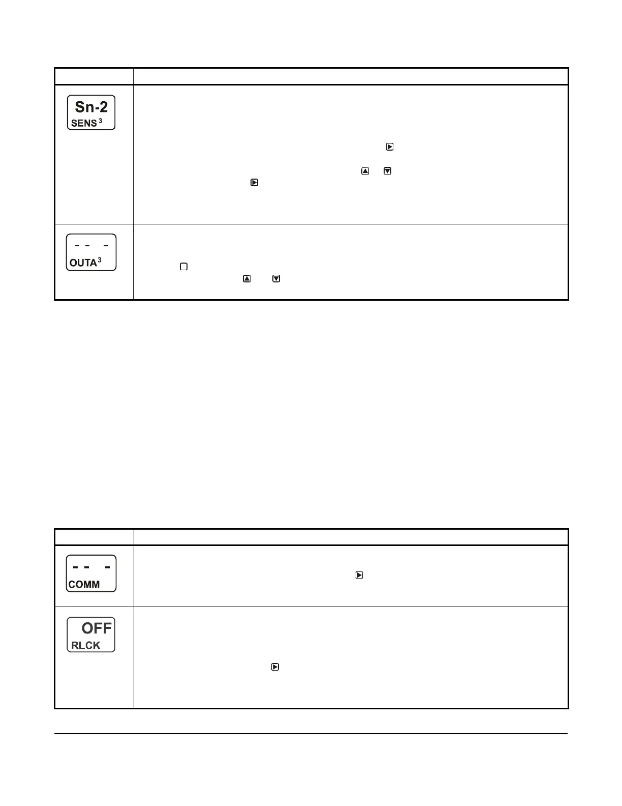
Edit Sensor Selection Screen: This screen displays the sensor that this output currently references.
Typically, no action is taken in this screen. But if you need to change the sensor that this output
references, you can select a different sensor for this output in this screen.
Note: If you change the sensor that an output references to a sensor with a different Sensor Type, the
default setup values for the output change, and you must set up the output again.
11. If you are not changing this output’s sensor, simply press to save the current sensor selection and
return to the Analog Output Setup Start screen.
To change the sensor this output references, press or to select the new sensor that this output
references. Then press to save the new sensor selection and return to the Setpoint Selection
screen (SP or dSP). If the new sensor has a different Sensor Type from the previously referenced
sensor, repeat the output setup procedure for this output.
The screen example shows Sn-2 as the selected Sensor for Output 3.
Analog Output Setup Start Screen:
After you have set up this analog output, you can go to another Output Setup Start screen, the Sensor
Setup Start screen, or return to the Main screens.
12. Press to scroll through the remaining Output Setup Start screens and return to the Sensor Setup
Start screen, or press and simultaneously to return to the System 450 Main screens.
The screen example shows the Analog Output Setup Start screen for Output 3.
Table 11: System 450 Ethernet Network Setup Screen Information and Procedures (Part 1 of 2)
LCD Screen Name, Description or Function, User Action, and Example
Communications View and Setup Start Screen: From the Communications Setup Start screen, you can
access the communications screens for the control module with Ethernet communications.
1. In the Communications Setup Start screen, press to go to the Remote Network Access Lock
screen.
The screen example show the Communications Setup Start screen.
Remote Network Access Lock Screen: You can lock or unlock remote access (with Ethernet) to the
System, Sensor, and Network web pages in the control module’s web UI. When On is selected, the login
fields on the Home page are not available; remote users can access only the System 450 Home page and
view the system status. Select OFF to enable the login fields, which allow web users to log into the UI and
access the setup screens.
2. Select On or OFF and press
to save the selection and go to the next screen.
The screen example shows the Remote Network Access Lock is set to OFF, indicating that remote access
is permitted. Remote Access refers to the ability to make configuration changes to the device through the
Ethernet connection.
Table 10: System 450 Setup Screen Information and Procedures for Analog Output (Part 4 of 4)
LCD Screen Name, Description or Function, User Action, Example
M
 Loading...


