System 450™ Series Control Module with Ethernet Communications Installation Instructions
26
Setting Up Password Protection
System 450 communications control modules provide password-protected access to your System 450 control
systems. You can operate your control system with or without password protection.
There are two password types for accessing the local (touchpad) System 450 UI—a User level password and an
Administrator (Admin) level password. Both local UI passwords are four-digit values (0000 to 9999).
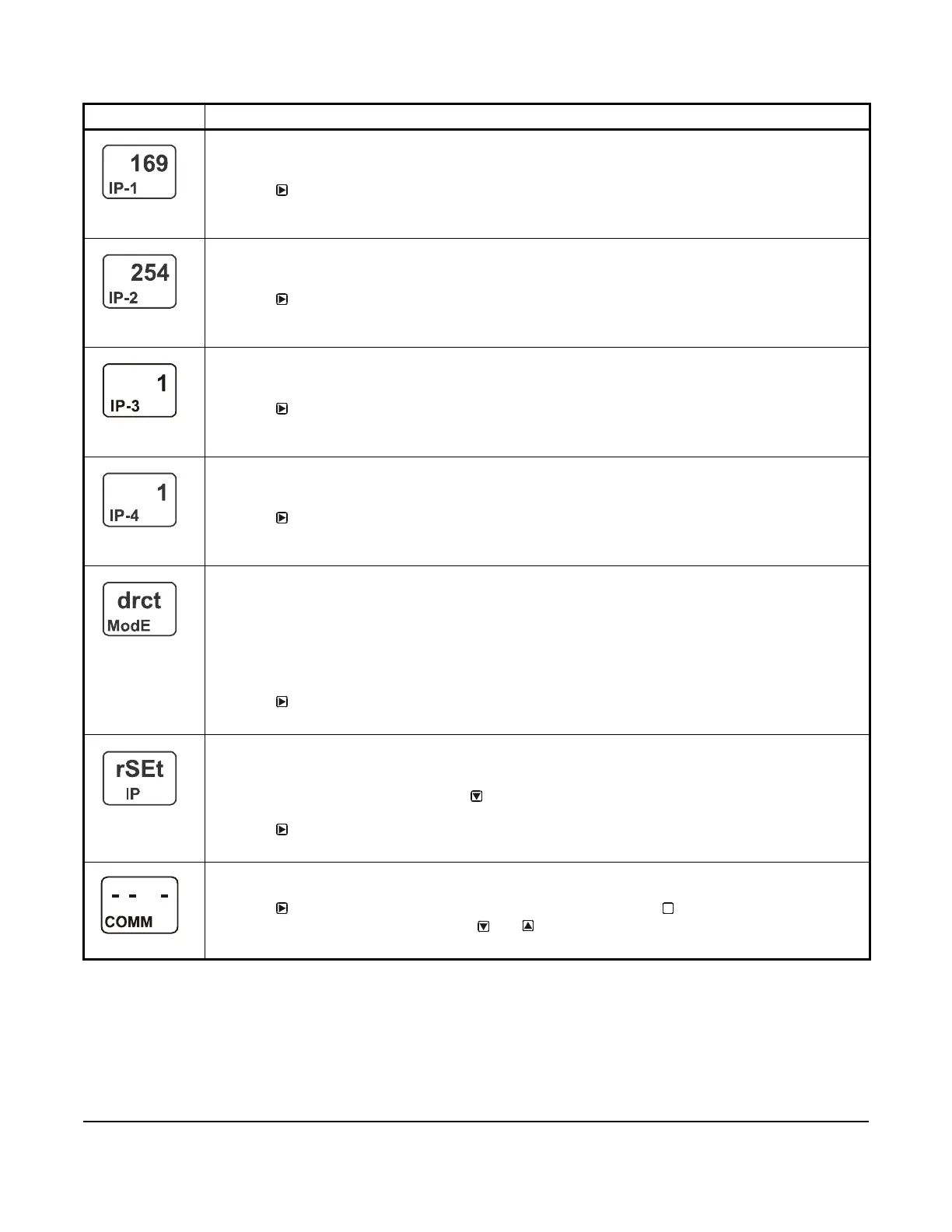
First IP-Address Octet Display Screen: Displays the first octet (one to three numerals) of the control
module IP address. This is a view-only screen. The control module’s IP address is set up using a client
computer connected to the control module.
3. Press
to go to the next screen.
The screen example shows the first IP address octet value 169 for the complete example IP address of
169.254.1.1, which is the factory-default IP address.
Second IP-Address Octet Display Screen: Displays the second octet (one to three numerals) of the
control module IP address. This is a view-only screen. The control module’s IP address is set up using a
client computer connected to the control module.
4. Press
to go to the next screen.
The screen example shows the second IP address octet value 254 for the complete example IP address
of 169.254.1.1, which is the factory-default IP address.
Third IP-Address Octet Display Screen: Displays the third octet (one to three numerals) of the control
module IP address. This is a view-only screen. The control module’s IP address is set up using a client
computer connected to the control module.
5. Press
to go to the next screen.
The screen example shows the third IP address octet value 1 for the complete example IP address of
169.254.1.1, which is the factory-default IP address.
Fourth IP-Address Octet Display Screen: Displays the fourth octet (one to three numerals) of the
control module IP address. This is a view-only screen. The control module’s IP address is set up using a
client computer connected to the control module.
6. Press
to go to the next screen.
The screen example shows the fourth IP address octet value 1 for the complete example IP address of
169.254.1.1, which is the factory-default IP address.
Network Address Mode Status Screen: Displays the Network Address mode that control module is
configured to operate in. This is a view-only screen. The three available modes are:
• drct ModE (Direct Connection mode)
• StAt ModE (Static IP Connection mode)
• Auto ModE (Automatically Obtain IP Address mode)
After you configure the network parameters for your control module in the web UI and reset the control to
implement your network settings, this screen displays the network address mode.
7. Press
to go to the next screen.
This screen example shows that the communications control module is in the Direct Connection mode.
Reset Default Network Configuration Screen: Allows you to restore all of the network configuration
parameters to their default values, and places the communications control module in the Direct
Connection mode.
8. While rSEt is blinking, press and hold for 5 seconds to restore the control module’s network
configuration values to the original default values. When rSEt stops blinking, the reset is complete.
Press
to go to the next screen.
This screen example shows the Reset Network Configuration screen.
Communications Setup Start Screen: From the Communications Setup Start screen, you can access
the communications screens for the control module with Ethernet communications.
9. Press
to go to the Remote Network Access Lock screen, or press to scroll through the System
Setup Start screens, or press and hold and simultaneously to return to the Main screens.
This screen example show the Communications Setup Start screen.
Table 11: System 450 Ethernet Network Setup Screen Information and Procedures (Part 2 of 2)
LCD Screen Name, Description or Function, User Action, and Example
M
 Loading...


