System 450™ Series Control Module with Ethernet Communications Installation Instructions
6
Setup and Adjustments
System 450 Component Requirements
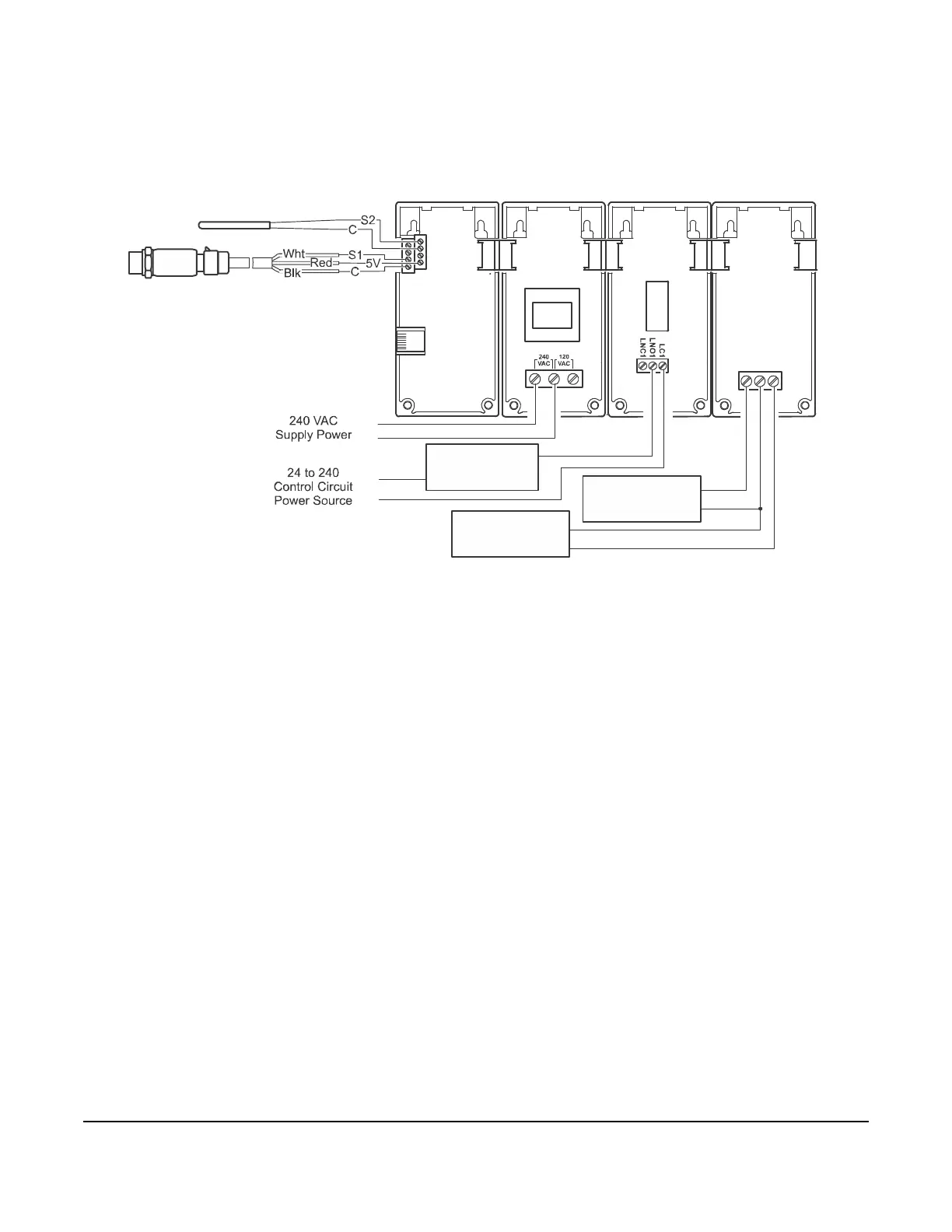
A System 450 control system consists of one control module, one to three control sensor inputs, and one to ten
outputs that provide on/off control or analog control. Figure 3 shows an example System 450 control system
module assembly, with two sensors and three outputs, connected to an Ethernet network.
Building a System 450 Module Assembly
To set up a System 450 module assembly:
1. Determine the controlled conditions, sensor types, and value ranges required for your application, and select
the appropriate System 450 sensor types.
2. Determine the number and type (relay or analog) of outputs required to control your application, and select the
appropriate System 450 control module and expansion modules to provide the outputs.
3. Assemble the control and expansion modules in the proper order, starting with the control module on the left.
Note: If you use a C450YNN-1C power module, it must be plugged into the control module. Plug in any
expansion modules to the right of the power module.
4. Apply supply power to the module assembly.
Note: After you power on your module assembly, you can set up your control system in the control module UI
before wiring the sensors or outputs to your assembly.
FIG:sys450_ethernet_app_example
C450CEN-x
AO2
COM
AO1
C450YNN-1
C450SBN-x
Expansion Module
Expansion Module
OUTA2, OUTA3
A99 Temperature Sensor
Control Sensor in UI Display
( Sensor Type)
Sn-2
F°
P499 Pressure Transducer
Control Sensor in UI Display
( Sensor Type)
Sn-1
P500
RJ45
Ethernet
Port
Cooling Equipment
Control Circuit
(24 to 240 VAC)
Condenser Fan 2
Speed Control
Analog Input Circuit
Condenser Fan 1
Speed Control
Analog Input Circuit
Figure 3: Example System 450 Control System with an Ethernet Communications Module
Controlling a Cooling System with Condenser Fan Speed Control