System 450™ Series Control Module with Ethernet Communications Installation Instructions
7
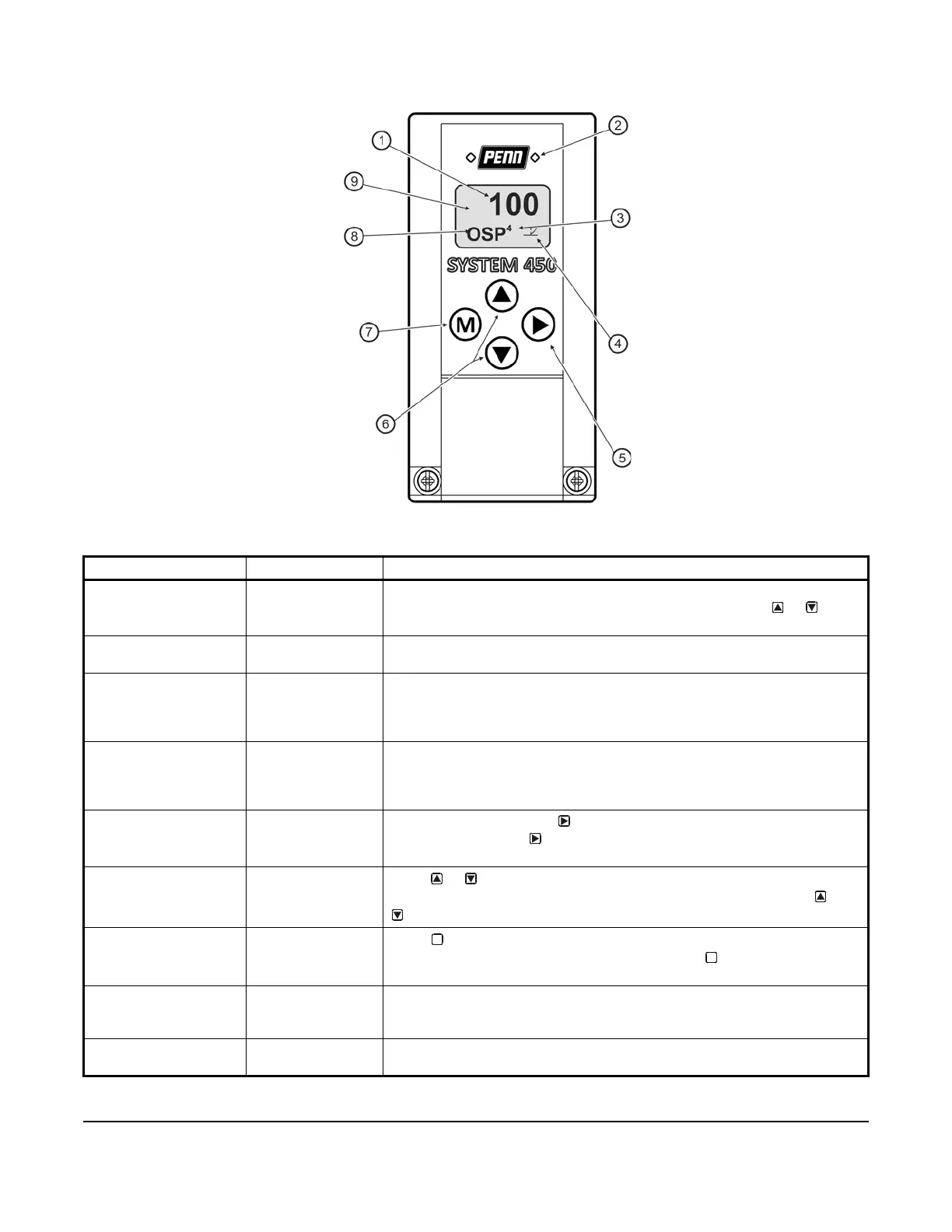
Table 2: System 450 Control Module Output Analog LEDs, LCD, Four-Button Touchpad User Interface
Callout Feature Description
1 Status or Setup
Value
Displays the current input status, output status, or setup parameter value for
the displayed input sensor, output, or setup parameter. Press or to
select a different parameter value when the value is flashing (100 = 100%).
2 LED Green LEDs on Relay Control Module and Relay Expansion Modules (only)
indicate if the associated relay output is on or off.
3 Output Number Displays a numerical value that identifies the output associated with the
status or setup value shown on the screen. Output numbers are
automatically determined by the outputs' physical positions (left to right) in
the module assembly (4 = Output 4).
4 Control Ramp Icon Displays whether an analog output (only) is set as direct-acting or reverse-
acting, and whether the output signal strength is at minimum or maximum
when the sensed property is at Setpoint. The control ramp icon displayed is
determined by the output's SP, EP, OSP, and OEP setup values.
5 Next Button
In the Main screens, press
to scroll through the system status screens. In
a setup screen, press
to save the (flashing) setup value and go to the
next setup screen.
6 Up and Down
Buttons
Press or to select a different value for any flashing value in the setup
value field. In the Main (sensor status) screens, press and hold both and
for 5 seconds to access the setup Start screens.
7 Menu Button
Press to move through the sensor and output setup start screens. When
moving through the status or setup screens, press to return to the status
start screen or setup start screen.
8 Status or Setup
Identifier
Displays the unit of measurement, output, sensor number, or setup
parameter for the displayed status or setup value. The setup identifier OSP
represents % output signal strength at setpoint.
9 LCD Backlit LCD screen. During normal operation, the LCD displays the Main
screens.
Figure 4: System 450 Communications Module LEDs, LCD, Four-Button Touchpad User Interface
M
M