System 450™ Series Control Module with Ethernet Communications Installation Instructions
44
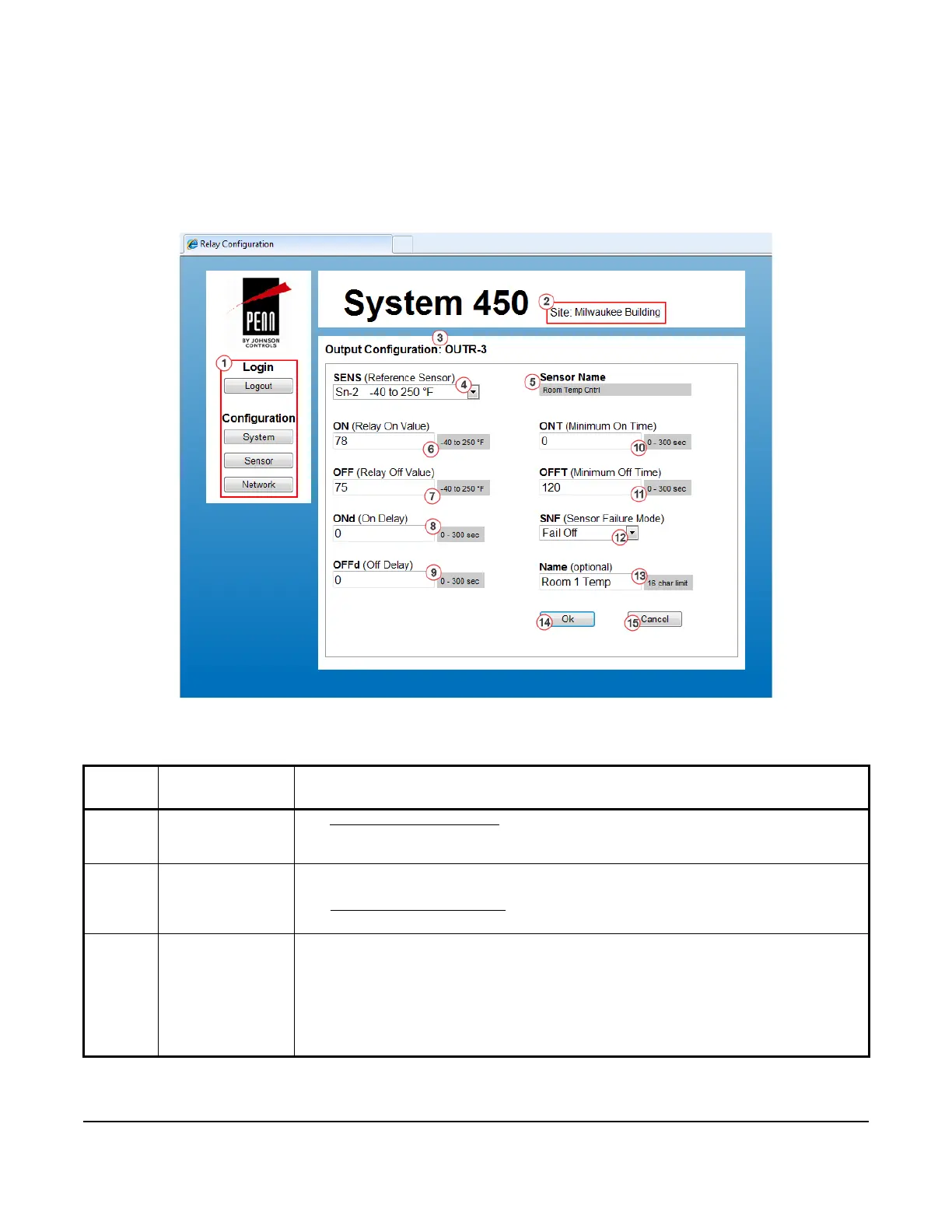
Relay Output Configuration Page
Figure 12 shows an example Relay Output Configuration Page for a System 450 control system that is set up and
operating.
Table 18 provides descriptions, user actions, and references for the items called out in Figure 12.
Table 18: System 450 Web UI Relay Output Configuration Page, User Actions, Descriptions, and
References (Part 1 of 3)
Callout
Number
Identifier / Item
Name
User Actions, Descriptions, References
1 Logout and
Configuration
Buttons
See System Configuration Page on page 35 for descriptions and user actions regarding the
System, Sensor, and Network buttons.
2Site NameDisplays the assigned site name. You can assign a website name on the Network
Configuration page.
See Network Configuration Page
on page 47 for more information on assigning a site
name.
3Output
Configuration:
OUTR-3
Displays the output type (OUTA or OUTR) and output number (-n), which are assigned by
the control module.
Note: When you first power on a System 450 module assembly, the control module
automatically detects the connected outputs and assigns an output type and number for
each connected output.
In this example, a relay output is detected and identified in the number 3 position in the
module assembly (OUTR-3).
Figure 12: System 450 Relay Output Configuration Page Example