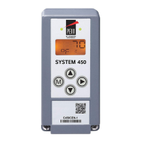
System 450™ Series Control Module with Ethernet Communications Installation Instructions
45
4 SENS (Reference
Sensor)
Click the drop-down menu to select the sensor that this output references. The reference
sensor selected for this output is displayed in this field.
Note: If Sn-1 and Sn-2 have the same sensor type, the Sn-d and HI-2 sensors are
available for selection. If Sn-1, Sn-2, and Sn-3 have the same sensor type, the
Sn-d, HI-2 and HI-3 sensors are available for selection.
After a sensor is selected for the output, the sensor number is displayed in the field, along
with the sensor’s sensor type and the usable range of values.
In this example, Sn-2 is the selected reference sensor and Sn-2 is configured as a °F
sensor type, which provides a -40 to 250°F temperature range.
5 Sensor Name Displays the assigned sensor name for the selected reference sensor.
Note: You can assign a 16-character (maximum) name for each sensor that you set up on
the Sensor Configuration page.
See Sensor Configuration Page
on page 37 for more information on assigning sensor
names.
In this example, the sensor name is Room Temp Cntrl.
6ON
(Relay On)
Enter the desired ON (Relay On) value for the relay output.
The range of usable values and units of measurement for ON are displayed in the gray box
to the right of the ON value field.
Note: The sensor type of the selected reference sensor determines the units of
measurement, the range of usable values, and the minimum differential between the ON
and OFF values.
In this example, the ON value is 78 (°F) and the usable range is -40 to 250°F.
7OFF
(Relay Off)
Enter the OFF (Relay Off) value for the relay output.
The range of usable values and units of measurement for OFF are displayed in the gray
box to the right of the OFF value field
Note: The sensor type of the selected reference sensor determines the units of
measurement, the range of usable values, and the minimum differential between the OFF
and ON values.
In this example, the ON value is 75 (°F) and the usable range is -40 to 250°F.
8ONd
(ON Time Delay)
Enter the ONd (ON Time Delay) value in seconds that you want the relay output to delay
going on after the Relay ON value is reached and maintained.
9OFFd
(OFF Time Delay)
Enter the OFFd (OFF Time Delay) value in seconds that you want the relay output to delay
going off after the Relay OFF value is reached and maintained.
10 ONT
(Minimum On
Time)
Enter the ONT (Minimum On Time) value in seconds (0 to 300). The ONT determines the
minimum time that the relay output remains on after reaching the ON point, regardless of
changing conditions.
11 OFFT
(Minimum Off
Time)
Enter the OFFT (Minimum Off Time) value in seconds (0 to 300). The OFFT determines the
minimum time that the relay output remains off after reaching the OFF point, regardless of
changing conditions.
12 SNF
(Sensor Failure
Mode)
Select from the drop-down menu how you want the relay output to respond when the
reference sensor or reference sensor wiring failure.
• If you choose Fail Off, the relay output goes off when the reference sensor or sensor
wiring fail.
• If you choose Fail On, the relay output goes on when the reference sensor or sensor
wiring fail.
In this example, Fail Off is selected.
13 Name
(Optional)
Assign a 16-character or less web UI name for the relay output.
Note: You are not required to assign an output name. When you assign a name, the
assigned name is displayed on the Overview page, the System Configuration page, the
Sensor Configuration page and the Output Configuration pages.
In this example, the name is Room 1 Temp.
Table 18: System 450 Web UI Relay Output Configuration Page, User Actions, Descriptions, and
References (Part 2 of 3)
Callout
Number
Identifier / Item
Name
User Actions, Descriptions, References

 Loading...


