System 450™ Series Control Module with Ethernet Communications Installation Instructions
5
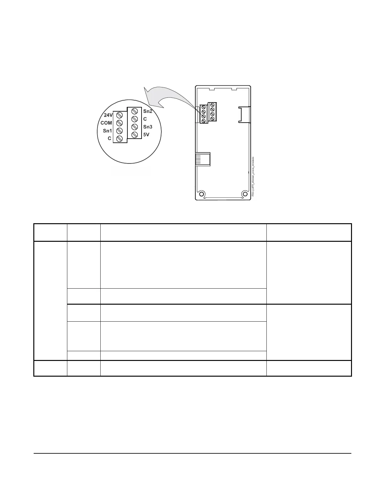
Table 1: System 450 Control Module with Ethernet Communications Wiring Information
Terminal
Block
Label Function, Electrical Ratings, and Requirements Recommended Cable
Type and Wire Sizes
Low-
Voltage
and Input
Sensors
Terminal
Block
24V Provides internal 24 VAC power at terminals for (humidity)
sensors when a C450YNN power module is connected in the
control system module assembly.
or
Accepts external 24 VAC (20–30 VAC) supply power for the
control system when a C450YNN power module is not
connected in the control system module assembly.
0.08 mm
2
to 1.5 mm
2
28 AWG to 16 AWG
COM Provides the common connection for 24 VAC power terminal for
either internally or externally supplied 24 VAC power (only).
S1, S2, S3 Accepts passive or active (0–5 VDC) input signals from control
sensors
1
.
1. For sensor wire runs greater than 50 ft (15.2 m) or where the sensor wiring is exposed to electromagnetic or radio
frequency interference, use shielded cable and connect the shield to a C (common) terminal on the control module.
0.08 mm
2
to 1.5 mm
2
28 AWG to 16 AWG
C, C Provide low-voltage common connections for the sensors
connected to the 5V, Sn1, Sn2, or Sn3 terminals (only).
Note: The two C terminals are used for sensor common
connections only. The two C terminals are connected internally.
5V Provides 5 VDC power for active sensors.
Ethernet
Port
Provides 8-Pin RJ45 modular jack for connecting to an Ethernet
network.
CAT 5 Straight-Through or
Crossover Cable
(C450CEN-1)
System 450 Control Module
with Ethernet Communications
6-Pin
System 450
Bus Connector
RJ45
Ethernet
Port
Common terminals (C)
are internally
connected.
Low-Voltage
Input Sensors and
Supply Power Terminals
Figure 2: C450CEN-x Control Module with Ethernet Communications
Showing Wiring Terminals