System 450™ Series Control Module with Ethernet Communications Installation Instructions
24
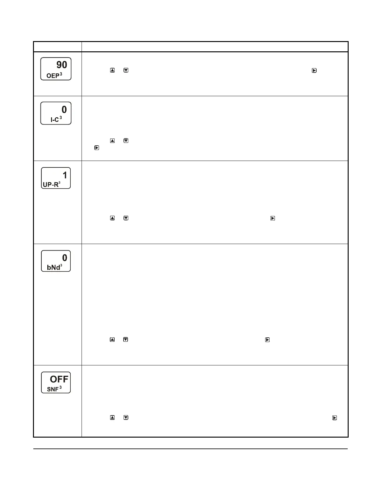
Output Signal Strength at End Point Selection Screen: Select the strength of the signal that this output
generates when the sensed condition is at the End Point value. The signal strength range is 0 to 100 (%).
6. Press or to select this output’s %Output Signal Strength at End Point value. Press to save
your selection and go to the Integration Constant Selection screen.
The screen example shows an OEP value of 90 (%) selected for Output 3. Therefore Output 3 generates
90% of the total signal strength (9 V or 18.4 mA) when the input is at the End Point value of 250 (psi).
Integration Constant Selection Screen: An integration constant allows you to set up proportional plus
integral control for this analog output. proportional plus integral control can drive the load closer to
Setpoint than proportional only control.
Note: Initially, you should select the I-C value of 0 (zero) for no integration constant. Refer to the System
450 Series Technical Bulletin (LIT-12011459) for more information on proportional plus integral control
and setting an integration constant in the System 450 UI.
7. Press or to select this output’s Integration Constant for proportional plus integral control. Press
to save your selection and go to the Output Update Rate Selection screen.
The screen example shows an I-C value of 0 (zero) selected for Output 3.
Output Signal Update Rate Selection Screen: Select the time interval in seconds at which the output
updates the output signal strength. The selected Output Signal Update Rate is the minimum time that the
output maintains a constant signal strength (regardless of the input signal) before updating the output
signal in response to the referenced input signal. The Output Signal Update Rate value range is 1 to 240
(seconds).
Note: The Output Update Rate is used to reduce excessive cycling or repositioning of controlled
equipment, such as valve and damper actuators. The Output Signal Update Rate feature can be used in
conjunction with the Output Signal Dead Band feature.
8. Press or to select this output’s Output Signal Update Rate. Press
to save your selection and
go to the Output Signal Dead Band Selection screen.
The screen example shows an Output Update Rate value of 1 (second), which is the default and lowest
update rate you can select.
Output Signal Dead Band Selection Screen: Select the Output Signal Dead Band value (as a percent
of the output signal strength range) to establish a dead band around the analog output signal strength.
The analog output responds to a changing input signal and updates the output signal strength whenever
the input signal moves outside of the selected Output Signal Deadband.
At each update of the output signal, the control determines if the calculated (input-induced) output signal
strength is within the selected Output Signal Dead Band or not. If the input-induced change of the output
signal strength is within the selected Output Signal Dead Band, the output signal strength is not updated
and remains unchanged. If the input-induced change of the output signal falls outside the Output Signal
Dead Band, the output signal strength is updated to the new signal strength value and the selected Output
Signal Dead Band is applied to the new signal strength value. The Output Signal Dead Band range is 0 to
50% of the OSP to OEP range.
Note: The Output Signal Dead Band is used to reduce excessive cycling or repositioning of controlled
equipment, such as valve and damper actuators.The Output Signal Dead Band feature can be used in
conjunction with the Output Signal Update Rate feature.
9. Press or to select this output’s Output Signal Dead Band. Press
to save your selection and go
to the Sensor Failure Mode Selection screen.
The screen example shows an Output Dead Band value of 0 (%), which is the default value and disables
the Output Dead Band feature.
Sensor Failure Mode Selection Screen: Select the output’s mode of operation if a referenced sensor or
sensor wiring fails. For outputs that reference functional sensors HI-2, HI-3, or Sn-d, the failure of any of
the referenced hard-wired sensors results in a functional sensor failure condition. The output operates in
the selected Sensor Failure mode until the failure is remedied. Sensor Failure mode selections for analog
outputs include:
• ON = Output generates the selected OEP signal strength during sensor failure.
• OFF = Output generates the selected OSP signal strength during sensor failure.
10. Press or to select this output’s mode of operation if the sensor or sensor wiring fails. Press
to
save your selection and go to the Edit Sensor Selection screen.
The screen example shows OFF selected as the Sensor Failure mode for Output 3.
Table 10: System 450 Setup Screen Information and Procedures for Analog Output (Part 3 of 4)
LCD Screen Name, Description or Function, User Action, Example
 Loading...


