System 450™ Series Control Module with Ethernet Communications Installation Instructions
36
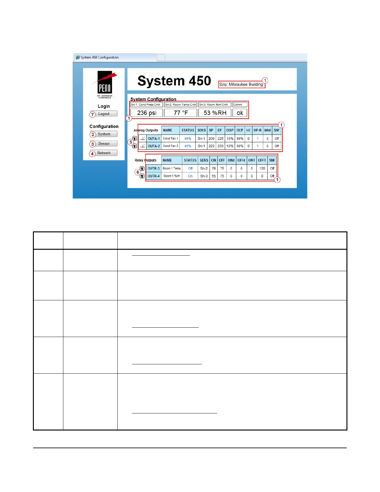
Table 15: System 450 Web UI System Configuration Page User Actions, Descriptions, and References (Part
1 of 2)
Callout
Number
Identifier / Item
Name
User Actions, Descriptions, References
1Site Name and
System Status
Information
See System Overview Page
on page 33 for information regarding the system status
information and site name. This information is the same on both the System Overview page
and the System Configuration page.
2System
Button
Click System to go to this System Configuration page.
Note: Clicking the System button on the System Configuration page simply refreshes the
page. Click the System button on any other configuration page to go to the System
Configuration page.
3Sensor
Button
Click Sensor to go to the Sensor Configuration page.
Note: You set up your control system sensors on the Sensor Configuration page. You
must set up the system sensors before you can set up the outputs.
See Sensor Configuration Page
on page 37 for more information on setting up your control
system sensors in the web UI.
4Network
Button
Click Network to go to the Network Configuration page.
Note: You set up your control system Network communications setting on the Network
Configuration page.
See Network Configuration Page
on page 47 for more information on setting up network
communications in the web UI.
5 Analog Output
Setup Access
Buttons
Click the button (showing a small wrench head) to the left of an Analog Output (OUTA-x)
status row to go to that analog output’s configuration page.
Note: The control module automatically detects the type and position of the control
system outputs in the module assembly and assigns an output type and unique output
number for each output in your system.
See Analog Output Configuration Page
on page 41 for more information on setting up
analog outputs in the web UI.
In this example, Outputs 1 and 2 are analog outputs.
Figure 9: System 450 System Configuration Page Example