System 450™ Series Control Module with Ethernet Communications Installation Instructions
38
Table 16: System 450 Web UI Sensor Configuration Page User Actions, Descriptions, and References (Part
1 of 3)
Callout
Number
Identifier / Item
Name
User Actions, Descriptions, References
1 Logout and
Configuration
Buttons
See System Configuration Page on page 35 for descriptions and user actions regarding the
System, Sensor, and Network buttons.
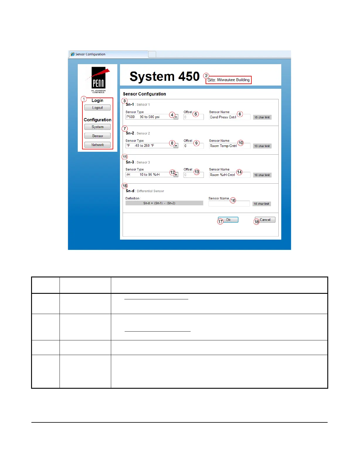
2Site NameDisplays the assigned site name. You can assign a website name on the Network
Configuration page.
See Network Configuration Page
on page 47 for more information about assigning a site
name.
3 Sn-1: Sensor 1 Sensor 1 Configuration Section: Select the Sn-1 sensor type, select an offset value (only if
Sn-1 is a temperature sensor), and assign a name for Sn-1.
4Sensor Type
(Sn-1)
Click the drop-down menu arrow to select the desired sensor type for Sn-1. The selected
sensor type provides the condition, the units of measurement, range of usable values,
resolution increments, and minimum proportional or control band for each output that
references Sn-1.
In this example, the P 500 sensor type is selected for Sn-1.
Figure 10: System 450 Sensor Configuration Page Example
 Loading...


