Johnson Controls Ducted Systems 6074816-UIM-A-0421
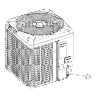
R-410A OUTDOOR SPLIT-SYSTEM
AIR CONDITIONING
MODELS: 13, 14, AND 17 SEER
YCD, YCE, YCG, YCS, YFD, YFE, TC3, TC4, TC7,
CC7, TW4, TF3, TF4, TCD, TCG, RAC13L, RAC14L,
RAC17L, RAW14L, RAC13F, RAC14F SERIES
INSTALLATION MANUAL
LIST OF SECTIONS
GENERAL . . . . . . . . . . . . . . . . . . . . . . . . . . . . . . . . . . . . . . . . . . . . . 1
SAFETY . . . . . . . . . . . . . . . . . . . . . . . . . . . . . . . . . . . . . . . . . . . . . . . 1
UNIT INSTALLATION . . . . . . . . . . . . . . . . . . . . . . . . . . . . . . . . . . . . 2
COIL METERING DEVICES . . . . . . . . . . . . . . . . . . . . . . . . . . . . . . . 6
EVACUATION . . . . . . . . . . . . . . . . . . . . . . . . . . . . . . . . . . . . . . . . . . 8
SYSTEM CHARGE . . . . . . . . . . . . . . . . . . . . . . . . . . . . . . . . . . . . . .8
ELECTRICAL CONNECTIONS . . . . . . . . . . . . . . . . . . . . . . . . . . . .10
INSTRUCTING THE USER . . . . . . . . . . . . . . . . . . . . . . . . . . . . . . .13
WIRING DIAGRAMS . . . . . . . . . . . . . . . . . . . . . . . . . . . . . . . . . . . .14
START-UP SHEET . . . . . . . . . . . . . . . . . . . . . . . . . . . . . . . . . . . . . .19
LIST OF FIGURES
Typical Installation Clearances . . . . . . . . . . . . . . . . . . . . . . . . . . . . . 3
Alternative Installation Clearances . . . . . . . . . . . . . . . . . . . . . . . . . . . 3
Installation of Vapor Line . . . . . . . . . . . . . . . . . . . . . . . . . . . . . . . . . . 4
Underground Installation . . . . . . . . . . . . . . . . . . . . . . . . . . . . . . . . . . 5
Heat Protection . . . . . . . . . . . . . . . . . . . . . . . . . . . . . . . . . . . . . . . . . 5
Recommended Distributor Adjustment . . . . . . . . . . . . . . . . . . . . . . . 6
Piston Installation . . . . . . . . . . . . . . . . . . . . . . . . . . . . . . . . . . . . . . . . 6
TXV Installation . . . . . . . . . . . . . . . . . . . . . . . . . . . . . . . . . . . . . . . . . 7
TXV Bulb and Equalizer line Installations . . . . . . . . . . . . . . . . . . . . . 7
Correct Bulb Location . . . . . . . . . . . . . . . . . . . . . . . . . . . . . . . . . . . . . 7
Vertical Temperature Bulb Orientation . . . . . . . . . . . . . . . . . . . . . . . . 8
Outdoor Unit Swing Away Control Box . . . . . . . . . . . . . . . . . . . . . . 10
Outdoor Unit Control Box (Single Phase - Smaller Base) . . . . . . . . 11
Outdoor Unit Control Box (Single Phase - Larger Base) . . . . . . . . .11
Outdoor Unit Control Box (Three Phase) . . . . . . . . . . . . . . . . . . . . .11
Typical Field Wiring (Air Handler / Electrical Heat) (Single-Phase) .12
Typical Field Wiring (Air Handler / Electrical Heat) (Three-Phase) . .12
Thermostat Chart - PSC Air Handler with Single Stage
Air Conditioner . . . . . . . . . . . . . . . . . . . . . . . . . . . . . . . . . . . . . . . . .12
Thermostat Chart - Single Stage PSC Furnace with Single Stage
Air Conditioner . . . . . . . . . . . . . . . . . . . . . . . . . . . . . . . . . . . . . . . . .13
Wiring Diagram - Single Phase 13 SEER and 14 SEER . . . . . . . . .14
Wiring Diagram - Single Phase 17 SEER . . . . . . . . . . . . . . . . . . . . .15
Wiring Diagram - Three Phase 13 SEER . . . . . . . . . . . . . . . . . . . . .16
Wiring Diagram - Three Phase 17 SEER . . . . . . . . . . . . . . . . . . . . .17
LIST OF TABLES
Application Limitations . . . . . . . . . . . . . . . . . . . . . . . . . . . . . . . . . . . . 2 R-410A Saturation Properties . . . . . . . . . . . . . . . . . . . . . . . . . . . . . . .9
SECTION I: GENERAL
These outdoor condensing units are designed to be connected to a
matching indoor coil. They are equipped with a filter-drier located in the
liquid line.
Units with quick-connect coupling connections are factory charged with
refrigerant to be matched with the appropriate pre-charged line set and
indoor coil.
SECTION II: SAFETY
This is a safety alert symbol. When you see this symbol on
labels or in manuals, be alert to the potential for personal
injury.
Understand and pay particular attention to the signal words DANGER,
WARNING, or CAUTION.
DANGER indicates an imminently hazardous situation, which, if not
avoided,
will result in death or serious injury.
WARNING indicates a potentially hazardous situation, which, if not
avoided,
could result in death or serious injury.
CAUTION indicates a potentially hazardous situation, which, if not
avoided
may result in minor or moderate injury. It is also used to
alert against unsafe practices and hazards involving only property dam-
age.
WARNING
Improper installation may create a condition where the operation of
the product could cause personal injury or property damage.
Improper installation, adjustment, alteration, service or maintenance
can cause injury or property damage. Refer to this manual for assis-
tance or for additional information, consult a qualified contractor,
installer or service agency.
CAUTION
This product must be installed in strict compliance with the enclosed
installation instructions and any applicable local, state, and national
codes including, but not limited to building, electrical, and mechanical
codes.
CAUTION
R-410A systems operate at higher pressures than R-22 systems. Do
not use R-22 service equipment or components on R-410A equip-
ment. Service equipment must be rated for R-410A.
!
!
!