4.4 Piping Connections
General Requirements
The following piping recommendations are intended to
ensure satisfactory operation of the unit. Failure to follow
these recommendations could cause damage to the unit, or
loss of performance, and may invalidate the warranty.
The maximum flow rate and pressure drop for the
evaporator and condenser must not be exceeded at
any time. Refer to Section 10 for details.
A flow switch must be directly in series with the evapo-
rator/ condenser and wired back to the control panel using
screened cable. For details refer to Electrical Connection
.This is to prevent damage to the evaporator/ condenser
caused by inadequate liquid flow. A paddle type flow swit-
ches are suitable for 10 bar working pressure.
The chilled water pump should be installed in the entering
water pipe. Pipework and fittings must be separately supp-
orted to prevent any loading on the unit. Flexible conn-
ections are recommended which will also minimize trans-
mission of vibrations to the building. Flexible connections
must be used if the unit is mounted on antivibration mounts
as some movement of the unit can be expected in normal
operation.
Pipework and fittings immediately next to the evaporator
should be readily dismantled to enable cleaning prior to
operation, and to facilitate visual inspection of the heat
exchanger nozzles.
A strainer must be mounted on the waterside of the
evaporator and condenser respectively, preferably of 40
meshes, fitted as close as possible to the liquid inlet conn-
ection, and provided with a local water cut-off switch.
The evaporator must not be exposed to too high flushing
velocities or debris deposited during flushing. It is recom-
mended that a suitably sized by-pass and valve arrang-ement
be installed to allow flushing of the pipework sys-tem. The
by-pass can be used during maintenance to isol-ate the
evaporator without disrupting flow to other units.
Thermometer and pressure gauge connections should be
provided on the inlet and outlet connections of the evap-
orator and condenser.
Drain and vent valves (by others) should be installed in the
connections provided in the cooler and condenser liquid
heads. These connections may be piped to drain if desired.
Any debris left in the water piping between the
strainer and cooler could cause serious damage to
the tubes in the cooler and must be avoided. The
installer/user must also ensure that the quality of
the water in circulation is adequate, without any
dissolved gases, which can cause oxidation of steel
parts within the cooler.
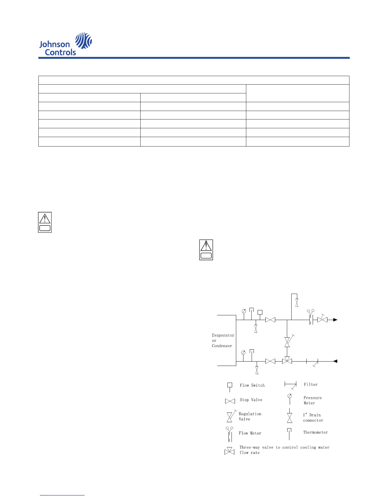
Fig 4-1 Diagram of cooling water and chilled wa-
ter pipe connection
YEWS-E Water Cooling Screw Chiller/Heat Pump
CAUTION
CAUTION
ISOLATORS SPRING
Kg
UP TO 3114
3115 TO 4453
4454 TO 5526
5527 TO 6927
6928 TO 8288
SYSTEM OPERATING WEIGHT
Lbs.
UP TO 6865
6866 TO 9818
9819 TO 12182
12183 TO 15272
15273 TO 18272
029W18479-001
029W18479-002
029W18479-003
029W18479-004
029W18480-001
PART NO
14

 Loading...


