leads with the red one as the center line. When the flow
increases, the red line contacts the yellow line; when the
flow decreases, the red line contacts the blue line. Use
supplied terminal screws for wiring. Use of other screws
may result in improper wiring.
No power shall be supplied during wiring to
guard against electric shocks or damages to the
equipment.
13.6 Steps to adjust the flow switch settings
1. Remove the HF68 housing.
2. Turn the adjusting screw clockwise to increase the flow.
If the flow needs to be decreased, turn the adjusting screw
anticlockwise.
3. Press the main lever for a few times to ensure the flow
switch setting is no less than the EXW setting. If there is
no click sound when the lever is Enteringed, turn the
adjusting screw clockwise until click sound appears.
If the water flow switch is used in chilled water
pipes, ensure its insulation as described in Water
Flow Switch Manual.
The water flow switch is set to the minimum at
the plant. It is forbidden to set it below the EXW
setting. Otherwise, it may cause that the flow
switch cannot reset during water cut-out.
CAUTION
CAUTION
WARNING
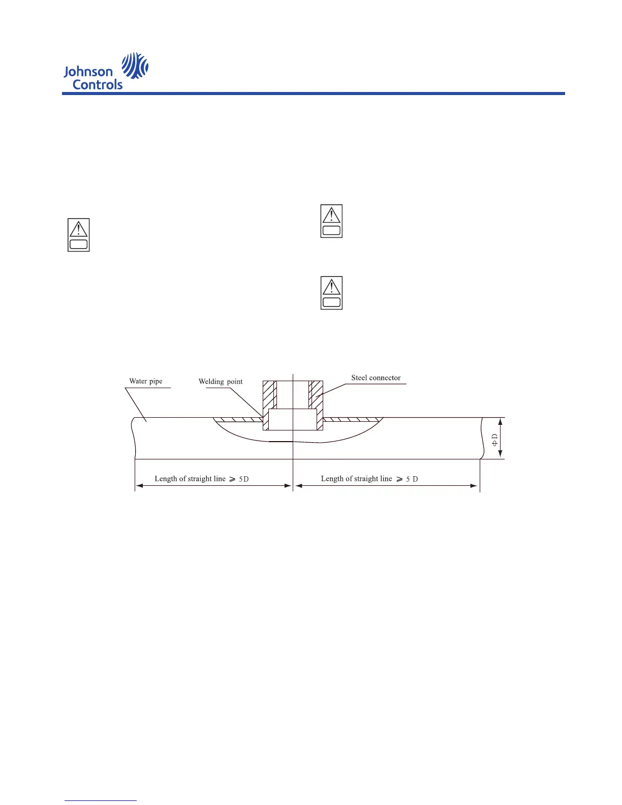
You MUST carefully read HF68 Flow Switch Manual before installing the flow switch and follow the instruction
strictly. If you have any question, please contact the nearest YORK Maintenance Center.
YEWS-E Water Cooling Screw Chiller/Heat Pump
73

 Loading...


