JOHNSON CONTROLS
56
FORM 150.62-NM6 (103)
NOTE:
Placement on a level surface of free of obstructions (including snow, for winter operation) or air circulation ensures rated performance, reli-
able operation, and ease of maintenance. Site restrictions may compromise minimum clearances indicated below, resulting in unpredictable
airow patterns and possible diminished performance. YORK’s unit controls will optimize operation without nuisance high-pressure safety
cutouts; however, the system designer must consider potential performance degradation. Access to the unit control center assumes the unit
is no higher than on spring isolators. Recommended minimum clearances: Side to wall – 2m; rear to wall – 2m; control panel to end wall
– 1.2m; top – no obstructions allowed; distance between adjacent units – 3m. No more than one adjacent wall may be higher than the
unit.
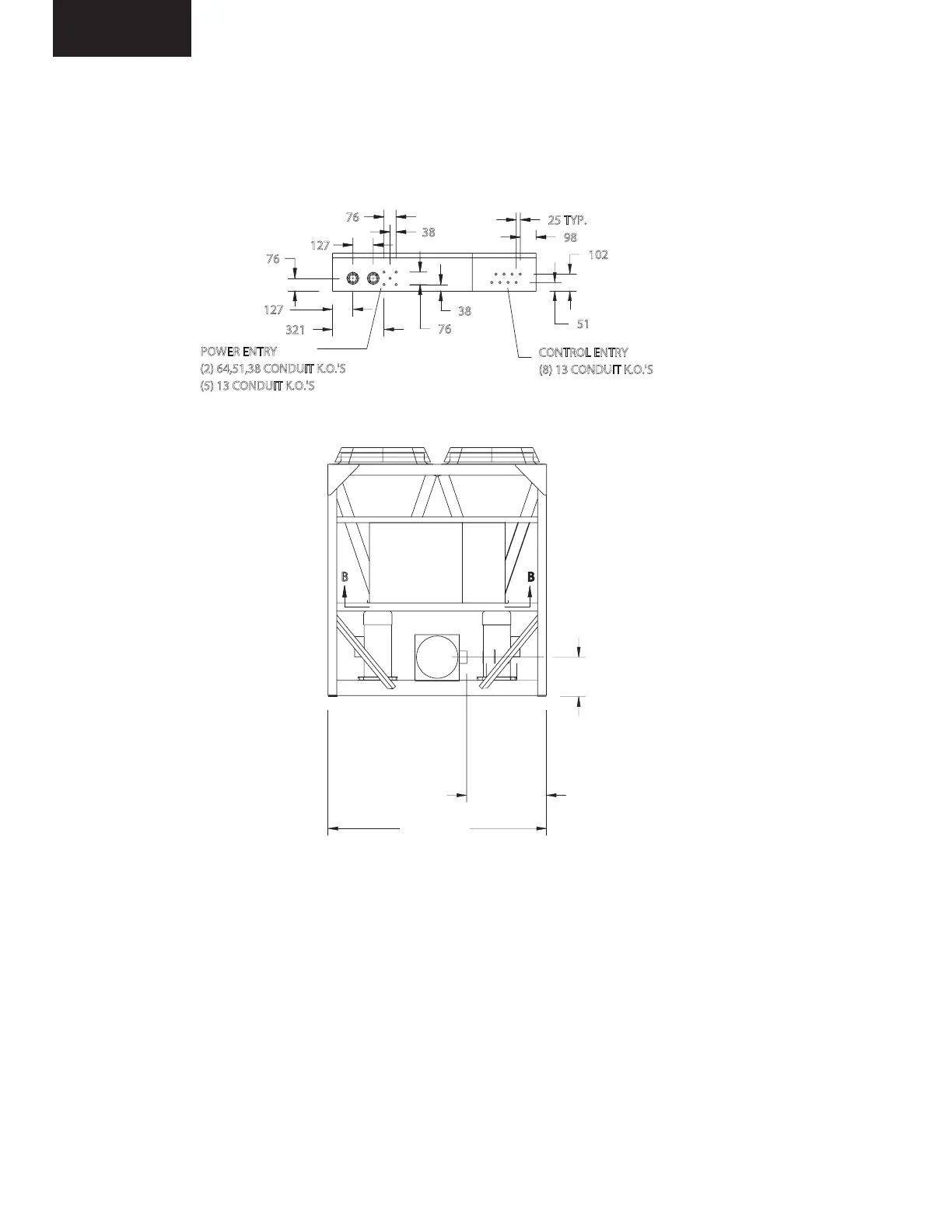
DIMENSIONS - YCAL0040-YCAL0060 (SI)
LD08706
(2) 64,51,38 CONDUIT K.O.'S
(8) 13 CONDUIT K.O.'S
(5) 13 CONDUIT K.O.'S
333
CONNECTION)
UNIT TO COOLER
626 (EDGE OF
VIEW A-A
2045
B B
VIEW B-B
POWER ENTRY
98
CONTROL ENTRY
51
321
127
127
76
76
76
38
38
25 TYP.
102
NOTE: All dimensions are in mm unless specied otherwise.
Installation

 Loading...


