JOHNSON CONTROLS
99
SECTION 5: TECHNICAL DATA
FORM 150.73-NM1
ISSUE DATE: 07/03/2024
55
VMC PART NUMBER VMC ISOL. COLOR WEIGHT RANGE (LB) WEIGHT RANGE (KG)
Y2RSI-2D-460 GREEN Up to 391 Up to 177
Y2RSI-2D-460 GREEN Up to 391 Up to 177
Y2RSI-2D-710 DARK BROWN 392 to 604 178 to 274
Y2RSI-2D-870 RED 605 to 740 275 to 336
Y2RSI-2D-1200N RED/BLACK 741 to 1020 337 to 463
Y2RSI-2D-1690 PINK 1021 to 1437 464 to 652
Y2RSI-2D-2640N PINK/GRAY 1438 to 2244 653 to 1018
Y2RSI-2D-2870N PINK/GRAY/ORANGE 2245 to 2618 1019 to 1188
Y2RSI-2D-3280N PINK/GRAY/DK.BROWN 2619 to 3740 1189 to 1696
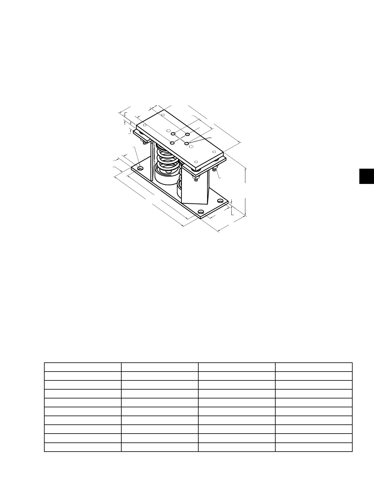
2 in. deflection seismic isolator cross-reference
Y2RS
LD13761A
12"
5"
2-3/4"
12-1/4"
8-3/8"
OPER.
HEIGHT
14"
5/8"
3/8"
Ø3/4"
TYP.(4)
3-1/2"
5/8-11UNC
TYP. (4)
2-3/4"
3/4"
7/8"
3/8" GAP
1/2" LIMIT
STOP &
NUT
NOTES:
1. ALL DIMENSIONS ARE IN INCHES, INTERPRET PER ANSI Y14.
2. STANDARD FINISH: HOUSING-POWDER COATED (COLOR:BLACK), SPRING-POWDER COATED (COLOR: SEE T
HARDWARE ZINC-ELECTROPLATE.
3. EQUIPMENT MUST BE BOLTED OR WELDED TO THE TOP PLATE TO MEET ALLOWABLE SEISMIC RATINGS.
4. ALL SPRINGS ARE DESIGNED FOR 50% OVERLOAD CAPACITY WITH EXCEPTION OF THE 2D-3280N & 2D-2870
5. REFER TO PAGE FOR INSTALLATION INSTRUCTIONS.
6. CONSULT FACTORY FOR CONCRETE INSTALLATION.
NOTES:
1. All dimensions are in inches, interpret per ANSI Y14.
2. Standard nish: housing-powder coated (color: black), spring-powder coated (color: see T hardware zinc-electroplate.
3. Equipment must be bolted or welded to the top plate to meet allowable seismic ratings.
4. All springs are designed for 50% overload capacity with exception of the 2D-3280n and 2D-2870.
5. See the following page for installation instructions.
6. Consult factory for concrete installation.




 To Next Page