ALIGNMENT PROCEDURE
6-5
3. If the receiver squelch adjustment will be made,
connect a SINAD meter to the Speaker Audio Out
jack on the RPI (see Figure 6-3). This is a low level
fixed audio output, and a 2.6 mm (3/32”) phone jack
is used.
4. Connect a wattmeter and a suitable load to the
antenna jack of the transceiver for the transmitter
tests. For the receiver tests, connect the signal
generator to the antenna jack through a 6 dB or
greater isolation pad.
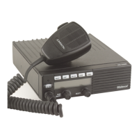
Figure 6-3 RPI Front Panel
6.4.2 STARTING AND CONFIGURING PCTUNE
1. Start the program as described in Section 6.1.2 and
turn transceiver power on. Select Transfer > COM
Port and make sure that the correct serial port and
the 19200 baud rate are selected (see Section 6.3.3).
2. Select the Radio menu and make sure the correct
radio series (53xx) is selected (see Section 6.3.2).
3. Select Transfer > Partial Tune and click the button
for the desired Test Category.
4. Follow the instructions displayed on the screen to
complete the various adjustments required for a
particular setting. Then repeat for other applicable
Test Categories. (The “Pendulum” test sets the
TCXO frequency.)
6.5 DIGITAL PERFORMANCE TESTS
6.5.1 GENERAL
This section describes how to check the perfor-
mance of the radio on digital Project 25 channels. The
PCTune software includes a Tools > Tx/Rx Tests menu
that displays the screen used for these tests.
• To perform these tests, a Digital Communication
Analyzer such as Motorola R2670 or IFR 2975 is
required.
• These tests follow the TIA-102-CAAA-A “Digital
C4FM/CQPSK Transceiver Measurement
Methods” specification. Refer to that document for
more information.
• A P25 conventional channel preprogrammed by the
PCConfigure software is used for testing. The
PCTune software does not select a specific test
channel. The test channel must be programmed with
the following options:
NAC - 293 (hex)
TGID (Talk Group ID) - 1
Frequency - Any frequency in radio operating
band
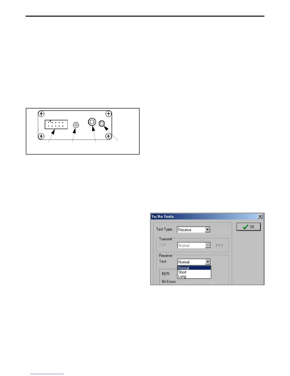
6.5.2 RECEIVE TEST SETUP
1. Connect the test setup and start and configure the
PCTune software as described in Section 6.4. Select
the Tools > Tx/Rx Tests menu to display the Tx/Rx
Tests screen. Then in the Test Type drop-down list
select Receive to display the following screen.
2. Connect the Digital Communication Monitor to the
antenna jack using a 6 dB or greater isolation pad.
Set the Monitor output for the “1011” test pattern.
6.5.3 RECEIVE SENSITIVITY TEST
1. A tone should be heard from the radio speaker if the
analyzer is set properly. Select the “Short” or
Front
Panel
10-Pin Radio Cable
Connector
Power
Indicator
Mic Audio In
Jack
Spkr Audio
Out Jack
 Loading...