ALIGNMENT PROCEDURE
6-6
“Long” test in the Test drop down list and the radio
should mute.
2. Set the analyzer output level for 0.35 µV (–116
dBm) at the receiver antenna jack
. The BER (Bit
Error Rate) should be 5% or less. (This is a ratio of
the receive bit errors to the total number of bits
transmitted.)
3. Increase the analyzer output level to 1000 µV (–47
dBm). The BER rate should be less than 0.01%.
This is the BER Rate Floor.
6.5.4 TRANSMITTER TESTS
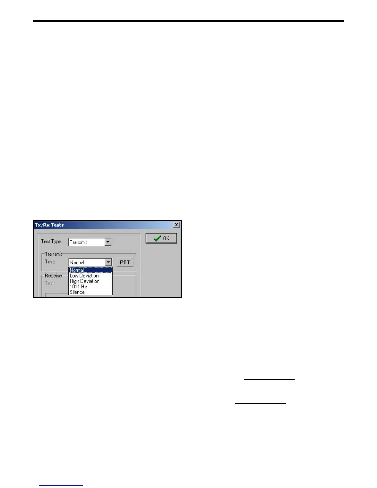
1. If applicable select the Tools > Tx/Rx Tests menu to
display the Tx/Rx Tests screen. Then in the Test
Type drop-down list select Transmit to display the
following screen. Connect a dummy load to the
radio antenna jack. Monitor the transmit signal with
the Digital Communication Monitor.
2. Select the Low Deviation test and set the analyzer
as required to measure transmitter deviation. This
test generates continuous repetitions of bits
10100000. Deviation should be 848-1037 Hz.
3. Click the “PTT” button to transmit the tone. When
finished, click that button again to turn the
transmitter off.
4. Select the “High Deviation” test which transmits a
standard transmitter test pattern. Deviation should
be 2544-3111 Hz.
5. The “1011 Hz” test transmits a standard 1011 Hz
tone similar to that used for the receiver test. This
tone can be used to check the operation of other
radios.
6. The “Silence” test transmits a standard silence test
pattern which produces no receive audio output by
the receiving radio. This tone can also be used to test
other radios.
7. Select “Normal” to transmit a standard voice signal
by speaking into the radio microphone.
6.6 ANALOG PERFORMANCE TESTS
6.6.1 GENERAL
The PCTune software is not used for analog
channel performance testing. Simply program the
desired channels using the PCConfigure software as
described in Section 4. The RPI is still required to
monitor the audio output signal from the radio.
Depending on the application, 12.5 kHz, 25 kHz,
and NPSPAC (800 MHz) test channels may need to be
programmed. Also, test channels programmed with or
without Call Guard
®
(CTCSS/DCS) squelch control
may be required.
6.6.2 RECEIVER PERFORMANCE TESTS
1. Connect a signal generator to the antenna jack using
a 6 dB or greater pad. Set the output for the channel
frequency, modulated with 1 kHz at the following
deviation:
12.5 kHz Channels - 1.5 kHz
25 kHz Channels - 3.0 kHz
800 MHz NPSPAC Channels - 2.4 kHz
2. Connect a SINAD meter to the receive audio jack of
the RPI (see Figure 6-3) This is a low level fixed
audio output.
SINAD Sensitivity
3. Set the signal generator output level for 1000 µV
(–47 dBm) at the antenna jack
.
4. Decrease the signal generator output to obtain 12 dB
SINAD. The signal generator output should be 0.35
µV (–116 dBm) or less for 25 kHz channels, or 0.50
µV (–113 dBm) or less for 12.5 kHz channels.
 Loading...