20
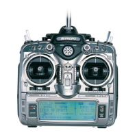
XP652 MANUAL Airplane
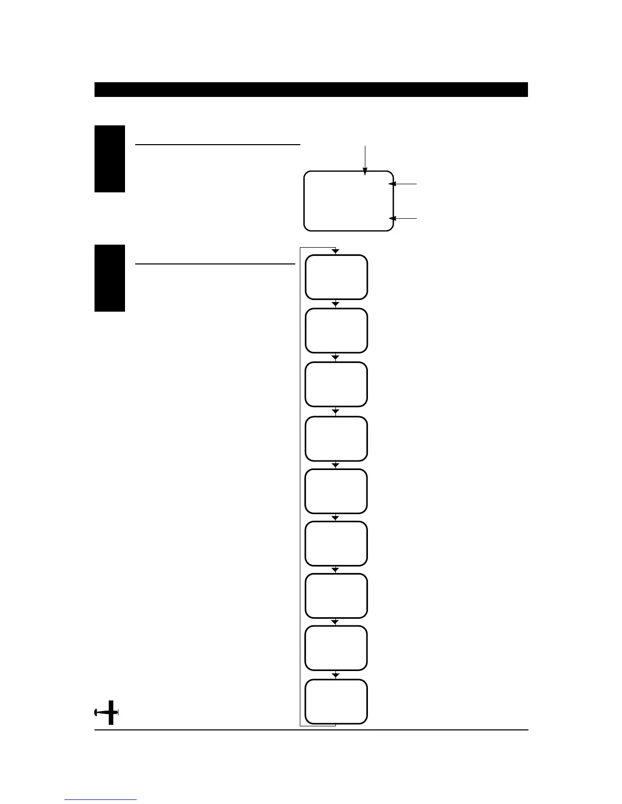
When the power switch is turned on the screen
will read as shown here in the diagram. This
screen is referred to as the normal display.
To enter the system mode, press the MODE
and CHANNEL buttons simultaneously while
you turn on the transmitter. You can now
select any of 7 system mode functions shown
here in the flow chart. To exit the system mode,
press the MODE and CHANNEL buttons
simultaneously or turn off the transmitter. Press
the mode button to move through the system
mode functions. Information for each function is
located on the page number listed next to the
function name.
SYSTEM MODE
CHAPTER 5:INPUT MODE AND FUNCTION
•
Airplane
5.2
NORMAL DISPLAY5.1
I
MD
L
I
-
I
PP
M
C
L
FSM
AC
TYP
AC
RST
E.A
SW
D/R
OF
W
N
G
MIX
MODEL TYPE SELECTION Page 22
DATA RESET Page 23
DUAL RATE
SWITCH SELECTION Page 24
Page 25
WING TYPE
SELECTION
FPR FLAPERON
MODEL SELECTION Page 27
MODEL NAME ENTRY Page 28
MODULATION SELECTION Page 29
FAIL-SAFE
(Z-PCM MODE ONLY) Page 30
FAIL SAFE MEMORY
(S-PCM MODE ONLY) Page 32
V
OF
FSI