SUB TRIM USAGE AND MECHANICAL ADVANTAGE
MECHANICAL ADVANTAGE
SUB TRIM
A52
Sub Trims are intended for relatively minor adjustments
to servo linkages and not for major trim adjustments to
the aircraft. Using excessive sub trim percentages can
cause a loss in servo resolution, where the servo reaches
its travel limit and stops moving before the control stick
is fully deflected.
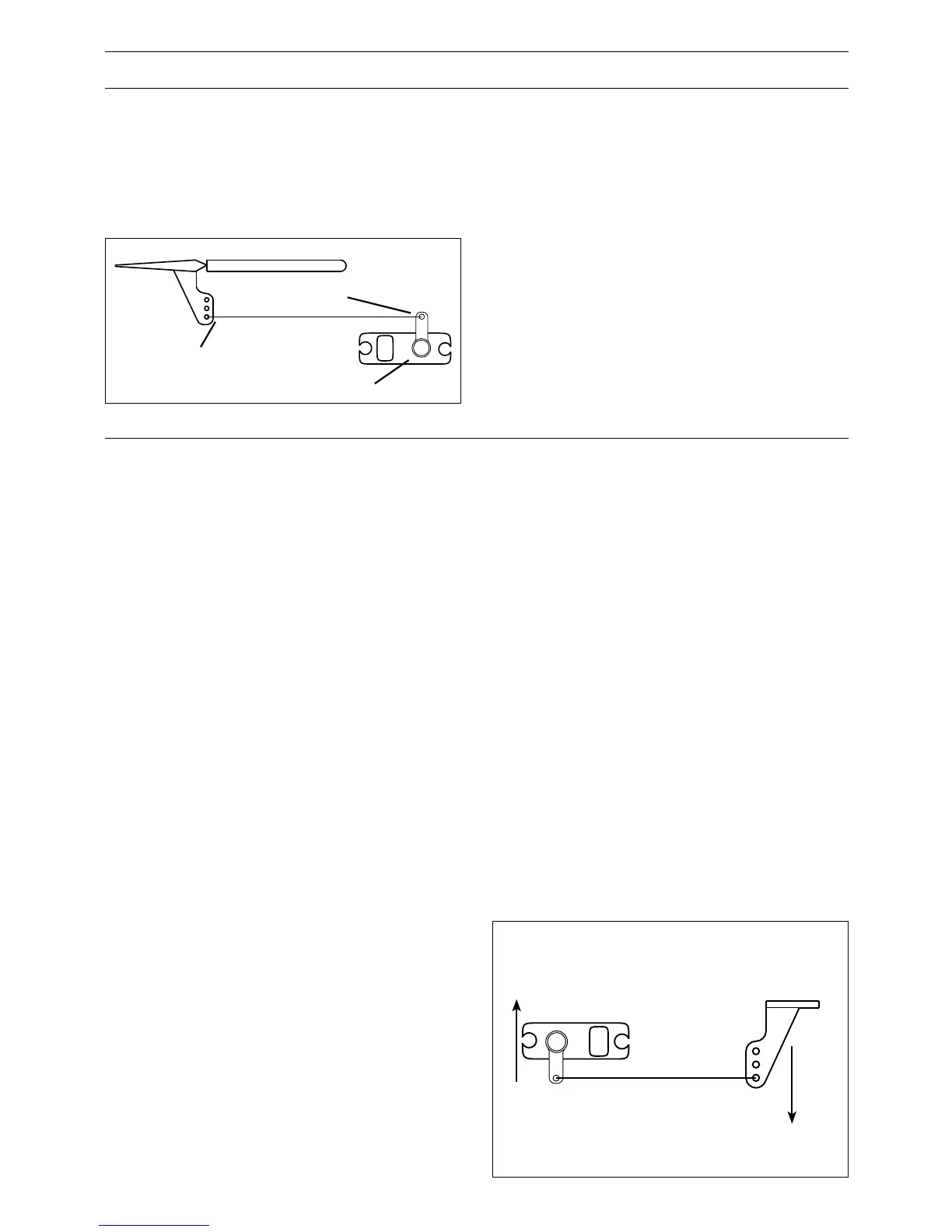
The diagram below illustrates an ideal servo/linkage setup
when the servo is at neutral (no sub trim and digital trims
centered). Notice that the servo arm is positioned at 90˚
or perpendicular to the servo. Also note that the linkage
or rod is attached at 90˚ to both the servo arm and the
control surface horn. This setup will result in the same
amount of throw in both directions (0 differential throw).
If the servo cannot be mounted parallel to the linkage/rod
then just make sure the servo arm is at 90˚ to the control
rod when the servo is at neutral.
Mechanical Advantage is a very important concept when
dealing with larger aircraft. It refers to the leverage that
the servo can exert on the control surface. Since the
control surfaces are rather large, it is important for the
servo to have enough mechanical advantage or leverage
to control them, regardless of the servo’s rated torque.
A large amount of torque is of little value if there is not
enough leverage to use it. Insufficient leverage can lead to
control surface flutter (usually a catastrophic event) and
blow-back, where the air flow pushes the control surface
backwards resulting in mushy or no control at higher
speeds.
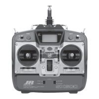
There are two ways to increase the mechanical advantage
of the servo. One is to make sure that the control horn
device, whether it be a horn as shown in the illustration
above or a bolt with a Rocket City-type fastener, is
long enough. The horn is the lever that the servo uses
to control the surface. The longer the horn, the more
leverage the servo has. It’s like a Lug Wrench – when you
can’t get a lug nut loose you put a piece of pipe over the
end of the lug wrench to extend the handle and that gives
you more leverage to break the lug nut free. It’s the same
thing—the lug nut is the control surface and you are the
servo trying to move it. As a general rule-of-thumb, try
to attach the linkage at the control surface so that it is at
least 1” away from the surface – longer is better.
The second way to increase the mechanical advantage
for the servo is to attach the linkage at the servo arm as
far inward (towards the servo arm retaining screw) as
possible while still providing enough throw. It’s the “lever
thing” again, but in reverse, as we are taking leverage
away from the control surface by providing it with a
shorter lever to work against the servo.
Ensure that the attach point is the same distance from the
hinge line for like surfaces (two Ailerons, two Elevators
and two Rudder horns). If the attach points are not the
same distance from the hinge line there will be unequal
throw and it will be more difficult to synchronize the
surfaces for equal deflection. This is especially critical
for the Rudder where two servos are attached to the same
surface – unequal throw will cause the servos to fight one
another causing excessive battery drain, and in severe
cases may cause servo damage.
Always try to use the maximum amount of Travel (100%)
that the radio provides. If it is too much travel, don’t
reduce the percentage of travel in the radio. Instead, move
the linkage further away from the hinge line at the control
surface and/or move the linkage inward on the servo arm
or use a shorter arm. If you use high percentages of travel,
you maintain resolution (fine movements of the stick
result in fine positive movements of the control surface).
When we decrease travel percentages, we lose resolution.
Linkage is 90 degrees
to control horn
Linkage is 90 degrees to servo arm
Servo arm is 90 degrees to servo
Greater
Mechanical
Advantage
Greater
Mechanical
Advantage