−5 −
(1)
(2)
(5)
(4)
(3)
(6)
(7)
(10)
(16)
(19)
(8)
(9)
(12)
(13)
(15)
(11)
(14)
(17)
(18)
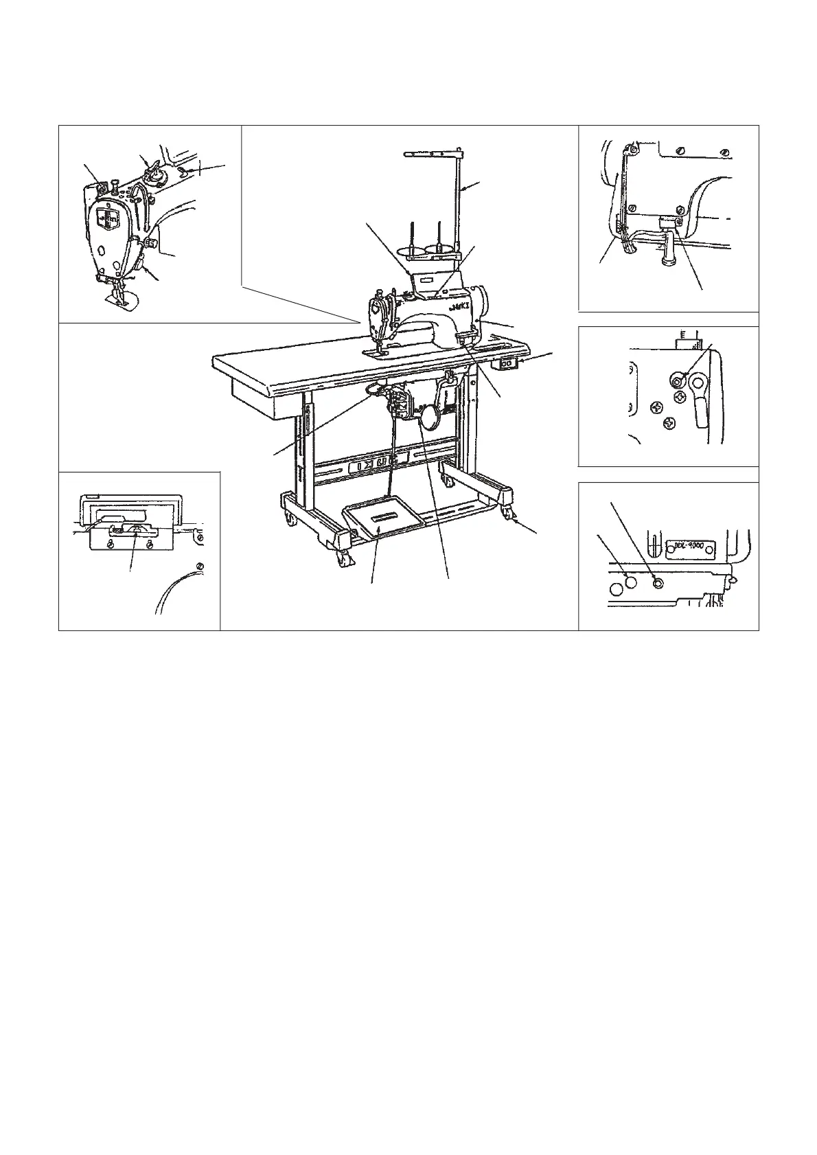
2. OPERATION
2-1 Configuration
(1) Power switch (8) Touch-back switch (14) Tension release change-over screw
(2) Operation panel (9) Wiper device (15) Micro-lifter screw
(3) Pulley cover (10) Screw for level adjustment (16) Under cover
(4) Thread stand of table/stand (Caster) (17) Oil hole
(5) PSC box (11) Resistor pack (18) Air vent
(6) Max. speed control knob (12) Bobbin winder
(19) Oil amount indication window (SS, SH)
(7) Operation pedal (13) Thread trimmer retainer
2-2 Check points before trial operation and operation
1) Make sure that the wiring to the control box is securely performed.
2) Make sure that the safety switch securely works. (Check whether the warning buzzer beeps when the sewing
machine head is tilted.)
3) Check that the red rubber cap of air vent (17) located on the front side of machine bed has been removed.
4) First, make the sewing machine run at low speed and check that there is no abnormal noise.
5) Depress the back part of the pedal and check that the thread trimmer securely functions.
6) For the SS type, check that oil is kept in oil tank.
7) For the SS type, check that the amount of oil in the hook is appropriate.
Fig. 1

 Loading...