Do you have a question about the JUKI DDL-9000C-S Series and is the answer not in the manual?
Details the different categories of risk indications used in the manual and product labels.
Explains the meaning of pictorial warnings and general warning labels found on the machine.
General guidelines for reading manuals, wearing safety gear, and consulting specialists.
Ensures safety by verifying correct installation and visibility of safety devices and labels.
Prohibits use for unintended applications or modifications to prevent accidents.
Ensures operators are trained and educated on machine operation and safety.
Lists operations requiring the machine's power to be turned off for safety.
Safe procedures for lifting, moving, and unpacking the machine to prevent accidents.
Safe methods for unpacking the machine, checking for damage and center of gravity.
Guidelines for safely installing the machine, including table, cable, wiring, and grounding.
Ensures connectors, cables, and safety devices are correctly installed and functional before operation.
Warnings about keeping hands away from moving parts and avoiding entanglement during operation.
Specifies the use of JUKI genuine oil and grease for lubrication and handling precautions.
Details safety during repair/maintenance, use of genuine parts, and authorized personnel.
Ensures operation in suitable environments, considering temperature, humidity, and noise.
Safety during disassembly/assembly and part replacement, using genuine parts.
Safety during adjustments, ensuring stable state, appropriate tools, and power off.
Safety during disassembly/assembly, using specified torque and checking rotation.
Safety during replacement of electrical parts, asking technicians, and handling wet hands.
Safety during adjustment of electrical components, power off, and using appropriate tools.
Safety during disassembly/assembly of electrical components, power off, and avoiding wet hands.
Details functions accessible at serviceperson levels 1 and 2 for the DDL-9000C-S model.
Procedure for adjusting feed dog height and gradient for optimal material feeding.
Critical adjustment of needle and hook for proper stitch formation.
Adjusts feed timing for optimal stitch quality and consistency.
Basic procedure for correctly inserting the bobbin into the bobbin case.
Adjusts the inner hook presser position for proper thread passing.
Details lubrication methods for different machine types and components.
Technical adjustments for motor origins and phase settings.
Adjusts the needle thread presser device for improved operability and thread control.
Adjustments for the thread trimming unit components for proper function.
Adjusts thrust values of the upper shaft to prevent rattles.
Adjustments for external parts like pulley cover and hand wheel.
Procedure for replacing the machine's motor.
Procedure for replacing the timing belt.
Instructions for safely replacing the machine's fuse.
Procedure for changing the machine's voltage setting.
Steps for safely removing the machine's control panel.
Details on screw types and positions for external parts attachment.
Cautions and procedures for using the dry hook component.
Adjustment and maintenance of the thread take-up lever mechanism.
Identifies and explains the function of each key on the DDL-9000C-S control panel.
Explains the Mode, Information, and Touch Panel functions for DDL-9000C-F.
Describes how to access serviceperson levels for functions on DDL-9000C-S.
How to access serviceperson levels for Mode and Information screens on DDL-9000C-F.
Details USB connectivity, including connector location, precautions, and specifications.
Procedures for data transfer using USB, including selection and setting.
Functionality to format USB devices, with procedures for different models.
Diagnostic function to check various machine operations and sensors.
Resets selected data to factory default, with procedures for different models.
Allows adjustment of the liquid crystal panel display brightness.
Assigns specific operations to touch-back switches.
Enables customization of panel keys by assigning desired functions.
Secures settings by enabling key-lock and setting a password.
Lists setting items and input ranges for pattern sewing mode.
Details setting items for polygonal-shape stitching, including step numbers.
Provides a list of memory switch data and initial values.
Explains the functionality of various memory switches.
Describes the control box composition with three types of board assemblies.
Procedure for removing the CTL board assembly by unscrewing and disconnecting.
Procedure for removing the PWR board assembly, including connector and screw removal.
Details the FLT-T board assembly for specific voltage specifications.
Details the FLT-S board assembly for specific voltage and CE specifications.
Procedure to set optional input/output functions on DDL-9000C-S.
Lists abbreviations, function items, and remarks for input signals.
Procedure to select and set input functions for input signals.
Procedure to select and set output functions for output signals.
Lists abbreviations, function items, and remarks for output signals.
Procedure to set optional input/output functions on DDL-9000C-F.
Shows the physical location of optional input-output connectors on the machine.
Describes the optional output connector CN61 and its signal allocation.
Describes the optional input-output connector CN51 and its signal allocation.
Details the PK70 connector wiring for variable speed, thread trimming, and presser lifter functions.
Provides wiring diagram for PK70 connector and suitable connectors.
Describes the optional output connector CN56 and its signal allocation.
Checks the amount of oil in the hook oil tank using the oil amount indicator.
Procedure for cleaning the machine, including removing parts and wiping dust.
Confirms hook oil tank level by checking oil amount indicator.
Steps for cleaning machine parts like needle, presser foot, and feed dog.
Greases needle bar lower bushing and presser bar bushing.
Applies grease to the feed bar mechanism, including grease groove.
Guidelines for grease replenishment and application to needle bar/presser bar bushings.
Procedure for greasing needle bar/presser bar bushings and handling excess grease.
Applies grease to feed bar mechanism parts during reassembly.
Applies grease to the roller, connecting section, and sliding groove of the face plate.
Procedure for greasing face plate parts and checking needle bar contact with oil wick.
Applies grease to the whole mechanical section inside the gear box.
Applies grease to gear box mechanism elements, link cover, and felt part.
Procedure for removing oil tank, float, lubrication pipe, and oil filter.
Instructions for installing the float correctly in the oil tank.
Procedure for putting and fixing the float case guide in the peep window.
Instructions for removing the peep window plate located behind the arm.
Procedure for cleaning the oil filter after removing the lubrication pipe.
Detailed procedure for adjusting the thread take-up lever mechanism, including parts replacement.
Step-by-step guide for replacing the motor, including coupling and setscrew removal.
Procedure for replacing the timing belt, including motor and solenoid removal.
Procedure to change power voltage by replacing the power cord.
Steps for pulling out the panel, removing cable connector, and reassembling.
Cautions for using dry hook, noting wear acceleration and contamination issues.
Cautions for installing dry hook and setting minimal oil lubrication.
Wiring diagram for the digital type control box and head section components.
Wiring diagram for the full digital type control box and head section components.
Troubleshoots stitch skipping at sewing start due to needle thread length or tension issues.
Troubleshoots stitch skipping due to knife timing, thread path, or feed dog issues.
Troubleshoots needle thread slipping off due to thread take-up picker or counter knife issues.
Troubleshoots thread tension problems due to hook presser or bobbin case issues.
Troubleshoots untrimmed needle thread due to stitch skipping or blunt knife blade.
Troubleshoots untrimmed bobbin thread due to moving knife or bobbin thread position issues.
Troubleshoots wiper interference with needle due to incorrect mounting height.
Addresses puckering due to thick needle, improper thread tension, or feed timing.
Troubleshoots puckering due to presser issues, rough presser finish, or material feed.
Troubleshoots uneven feed due to high feed dog, worn teeth, or incorrect pitch/tilt.
Addresses balloon stitches from low thread tension or improper thread take-up spring.
Troubleshoots balloon stitches due to thread take-up lever stroke or tension issues.
Troubleshoots balloon stitches due to hook timing, thread path, or bobbin issues.
Troubleshoots uneven feed due to high feed dog, worn teeth, or incorrect pitch/tilt.
Troubleshoots uneven feed due to presser issues, material feed, or sewing speed.
Reduces sewing speed if it is too high, potentially causing other issues.
Troubleshoots stitch skipping due to thread take-up spring or needle defects.
Troubleshoots stitch skipping due to hook issues, needle, or sewing speed.
Troubleshoots thread breakage due to needle installation, knife guide, or needle bar height.
Troubleshoots staggering stitches due to needle defects, tension, speed, or feed dog.
Troubleshoots staggering stitches due to presser, threading, or needle issues.
Troubleshoots irregular stitches from material stretching, backlash, or thread take-up lever issues.
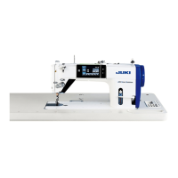
| Brand | JUKI |
|---|---|
| Model | DDL-9000C-S Series |
| Category | Sewing Machine |
| Language | English |