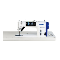
❸ Connector for a sewing machine for standing work (for the PK70)
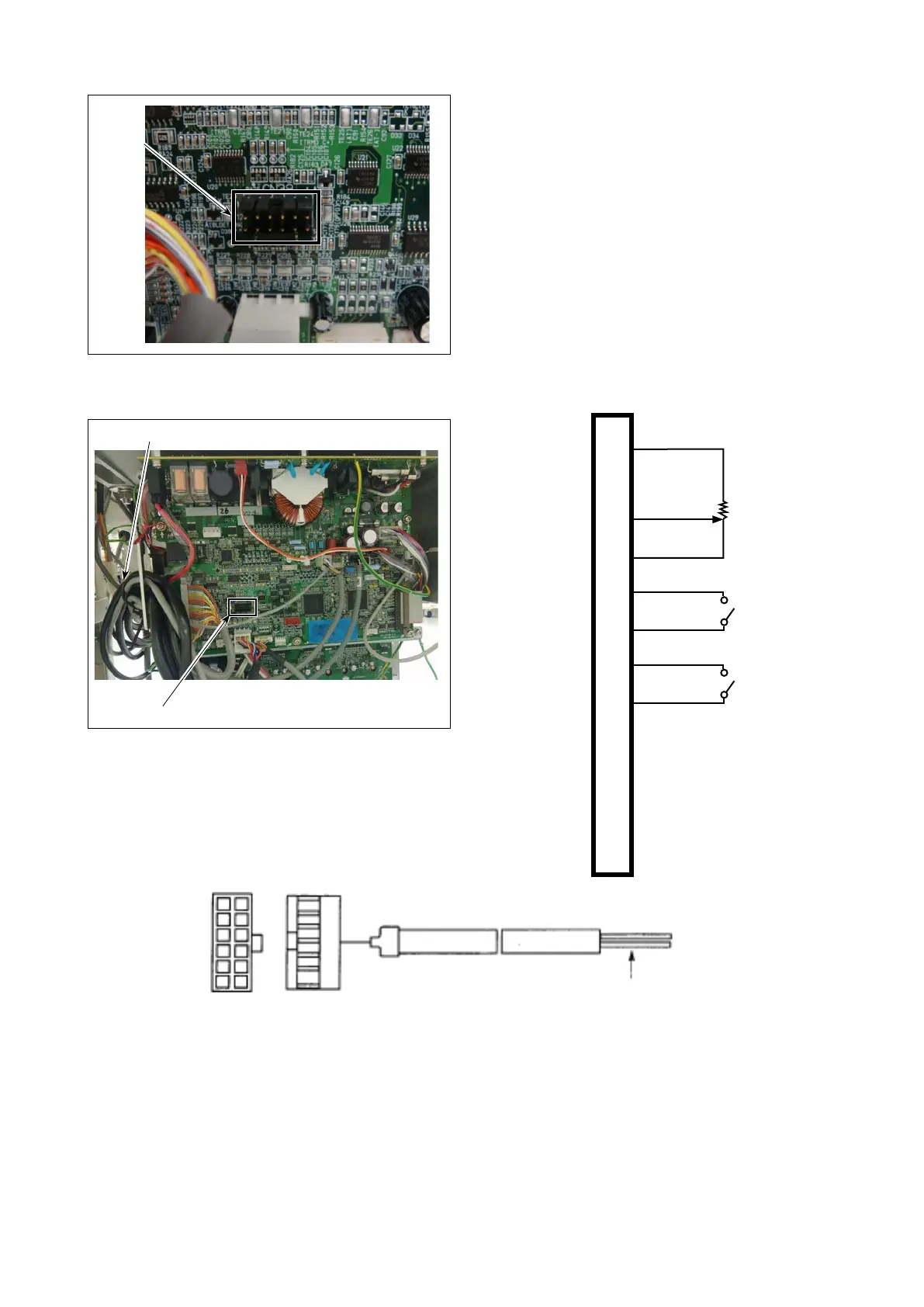
[Wiring diagram of variable pedal PK-70 and -71]
CN39
1
2
3
4
5
6
7
8
9
10
11
12
3.3V
Variable resistor
for speed
Switch for lifting
presser foot
Switch for thread
trimming
Switch for
high-speed
Switch for low-
speed
S GND
S GND
S GND
S GND
S GND
Brown
Orange
Yellow
Green
Blue
Perple
Gray
White
Light blue
Pink
Black
1
2
3
VR(1kΩ)
Used by
variable
voltage
between
1 to 2V
(Increasing
/ decreasing
speed)
Neutral
position is
1V ± 0.05V
(Between 3
to 4)
○ Power section A which is separated by respective signals with different colors A comes out from the relay
cord A asm. for the standing sewing machine. Connect switches and variable resistor for speed in accor-
dance with the wiring diagram.
○ Insert to the connector ❸ (CN39 : 12P) of standing sewing machine pedal in the PSC box and use it.
○ Tighten the cord of the PK70 together with other cords with cable clip band ❺ attached to the side of the
box after passing it through the cable clamp.
(Caution) In case of decreasing the speed of switch for high-speed, use the variable resistor for max-
speed limit mounted on the control panel.
A
1
1112
Approx. 1.5m
2
Relay cord A asm. for the standing sewing machine (Part No. M9701351AA0)
When you connect the PK70 made by Juki, connect
it to the CN39 of SC-951 (950) ❸.
* Variable speed using the variable pedal
* Thread trimming function using the pedal for a
thread trimming
* Pressure lifter function using the pedal for a pres-
sure lifter
Such above functions can be used.
The connector and each signal are being allocated
as follows:
❸
❸
❺
– 133 –

 Loading...