10
@1
@2
@4
@3
@6
@5
f
e
a
a
e
b
c
@8
@7
@9
#0
@7
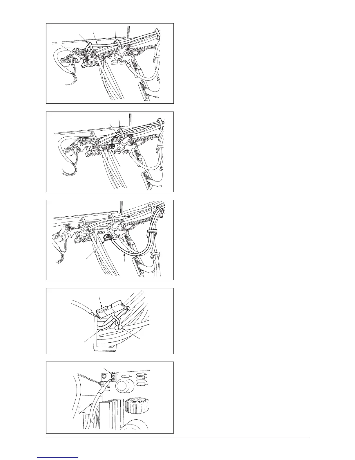
When the Auto-lifter (AK121) is used :
14) Insert white connector 2P cord
@
1 coming from
the machine head inside the electrical box through
front cover through hole B, pass it through cord
clamps “a”, “e” and “f”, and insert it into connector
CN40 @2.
When the bird’s nest prevention device is used
(CB type)
15) Insert white small connector 6P cord @3 coming
from the machine head inside the electrical box
through front cover through hole B, pass it through
cord clamps “a” and “e”, and insert it into connector
CN52 @4.
When foot pedal for standing work (PK70 or 71) is used :
16) Insert black connector 12P cord @5 inside the
electrical box through front cover through hole B
coming from the foot pedal for standing work, pass
it through cord clamps “b” and “c”, and insert it
into connector CN32 @6.
17) Connect white connector 2P of cord @7 supplied
as accessories to which red connector 2P and
white connector 2P are attached to white
connector 2P @8 of under cover of the machine
head.
Fix omega lock @9 supplied as accessories with
the neighboring cords and cord @7 as shown in
the figure.
18) Insert red connector 2P side of cord @7 supplied
as accessories to which red connector 2P and
white connector 2P are attached inside the
electrical box through front cover through hole, and
insert it into red connector CN25 #0.
Change the setting of function setting No. 23
from “0” to “1” after completing all set-up
procedure. For the details, see p.78 and p.81.