JUMO GmbH & Co. KG
Delivery address: Mackenrodtstraße 14
36039 Fulda, Germany
Postal address:
36035 Fulda, Germany
Phone: +49 661 6003-0
Fax: +49 661 6003-607
Email: mail@jumo.net
Internet: www.jumo.net
JUMO Instrument Co. Ltd.
JUMO House
Temple Bank, Riverway
Harlow, Essex CM20 2DY, UK
Phone: +44 1279 635533
Fax: +44 1279 635262
Email: sales@jumo.co.uk
Internet: www.jumo.co.uk
JUMO Process Control, Inc.
6733 Myers Road
East Syracuse, NY 13057, USA
Phone: 315-437-5866
1-800-554-5866
Fax: 315-437-5860
Email: info.us@jumo.net
Internet: www.jumousa.com
70357100T10Z002K000
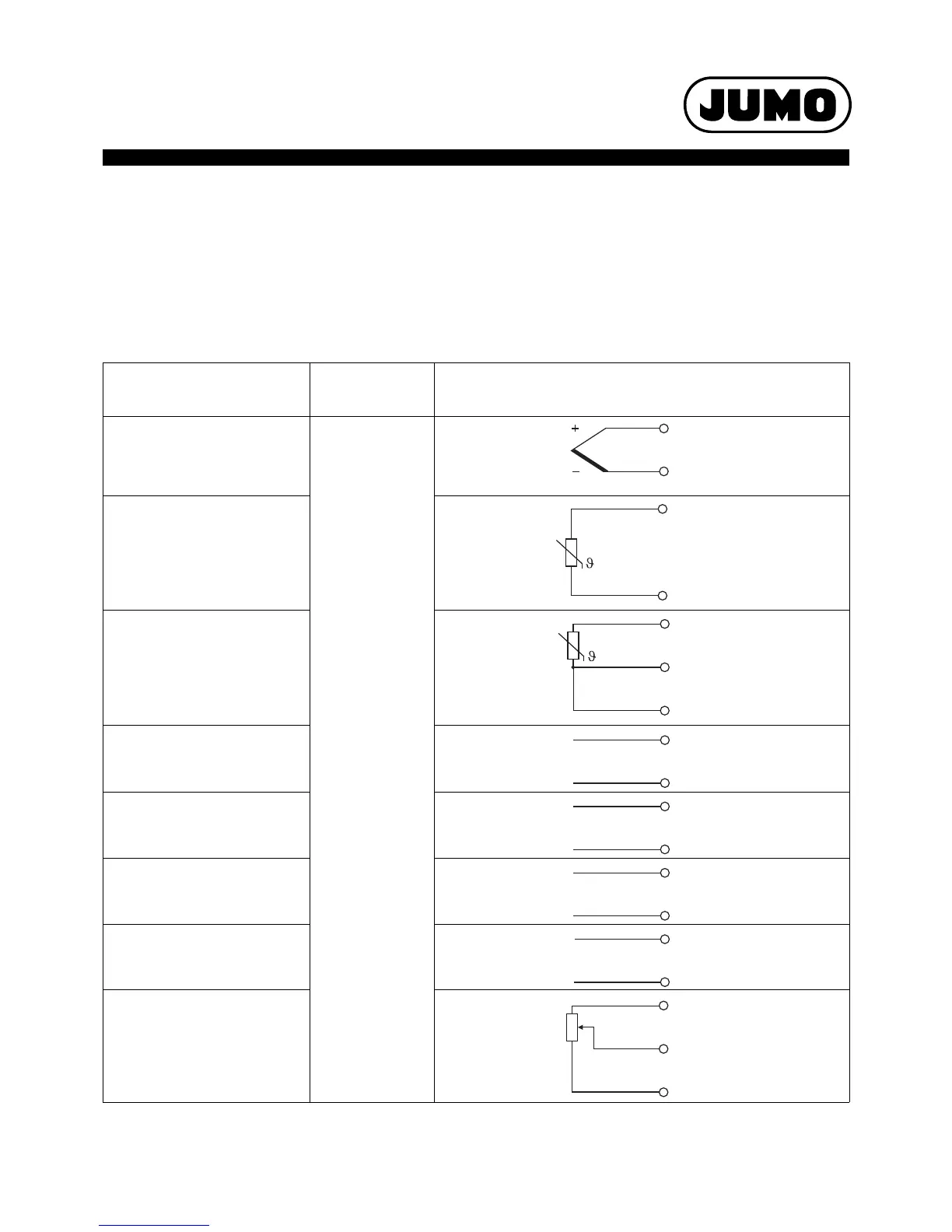
Connection diagram
The connection diagram included in the data sheet provides initial information about the connection options. Only use the installation instructions
or the operating manual for the electrical connection. The know-how and the correct technical implementation of the safety warnings/instructions
contained in these documents are the prerequisite for the installation, electrical connection, and initial start as well as for the safety during opera-
tion.
Analog inputs
Input IN8, IN9 as standard
Two analog inputs can be added to input (IN10), (IN11) optional boards
Connection (Connection ele-
ment)
Input
Symbol and terminal designation
Thermocouple (1) IN8
(2) IN9
(3) IN10
(4) IN11
3
4
RTD temperature probe
Two-wire circuit
2
4
RTD temperature probe
Three-wire circuit
2
3
4
Voltage DC 0(2) to 10 V 1
4
Voltage DC 0 to 1 V 2
4
Voltage DC 0 to 100 mV 3
4
Current DC 0(4) to 20 mA 3
4
Resistance transmitter
A = Start
E = End
S = Slider
2
3
4
 Loading...


