JUMO GmbH & Co. KG
Delivery address: Mackenrodtstraße 14
36039 Fulda, Germany
Postal address:
36035 Fulda, Germany
Phone: +49 661 6003-0
Fax: +49 661 6003-607
Email: mail@jumo.net
Internet: www.jumo.net
JUMO Instrument Co. Ltd.
JUMO House
Temple Bank, Riverway
Harlow, Essex CM20 2DY, UK
Phone: +44 1279 635533
Fax: +44 1279 635262
Email: sales@jumo.co.uk
Internet: www.jumo.co.uk
JUMO Process Control, Inc.
6733 Myers Road
East Syracuse, NY 13057, USA
Phone: 315-437-5866
1-800-554-5866
Fax: 315-437-5860
Email: info.us@jumo.net
Internet: www.jumousa.com
70357100T10Z002K000
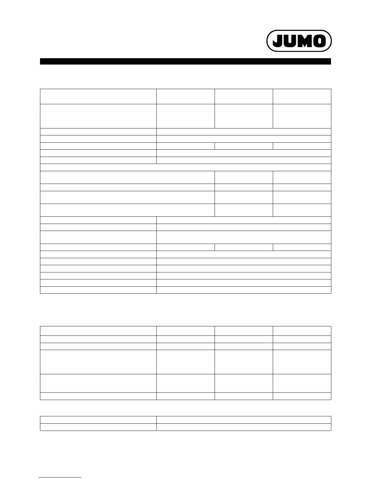
Standard signals
Measuring circuit monitoring
In the event of a malfunction, the outputs move to a defined (configurable) status.
Digital inputs
Description Measuring range Measuring accuracy
a
a
The accuracy values refer to the maximum measuring range. Smaller measuring ranges lead to reduced linearization accuracy.
Ambient
temperature influence
Freely scalable voltage
Input resistance R
E
> 500 k
Input resistance R
E
> 100 k
DC 0(2) to 10 V
DC0to1V
0 to 100 mV
0.1 % 100 ppm/K
Smallest measuring span 5 mV
Measuring range start/end Freely programmable within the limits in steps of 0.01 mV
Current (voltage drop 2V), freely scalable DC 0(4) to 20 mA 0.1 % 100 ppm/K
Smallest measuring span 0.5 mA
Measuring range start/end Freely programmable within the limits in steps of 0.01 mA
Limits in accordance with NAMUR recommendation NE 43 in case of deviation
above/below measured range
Signal type 2to10V Signal type 4to20mA
Measurement information M 1.9 to 10.25 V 3.8 to 20.5 mA
Failure information A for deviation below measured value/short-circuit ("NAMUR
Low")
1.8 V 3.6 mA
Failure information A for deviation above measured value/probe break ("NAMUR
High")
10.5 V 21 mA
Sampling rate Controller 1(2): 150 ms in total
Input filter Digital filter, 2nd order; filter constant can be set from 0 to 10.0 s
Galvanic isolation See Kapitel "Electrical data", Seite 10 and
Kapitel "Galvanic isolation", Seite 12
Resistance transmitter Min. 100 , max. 4 k0.5 %
b
b
The accuracy values refer to the maximum measuring range (initial resistance Ra + loop resistance RS + end resistance Re).
100 ppm/K
Connection type Resistance transmitter: three-wire circuit
Smallest measuring span 60
Sensor lead resistance Max. 10 per cable for two-wire and three-wire circuits
Resistance values Freely programmable within the limits in steps of 0.1
Sampling rate Controller 1(2): 150 ms in total
Input filter Digital filter, 2nd order, filter constant can be set from 0 to 10.00 s
Measuring probe Out of range Probe/cable short circuit Probe/cable break
Thermocouple is detected is not detected is detected
RTD temperature probe is detected is detected is detected
Voltage
2 to 10 V
0 to 10 V
0to1 V
is detected
is detected
is detected
is detected
is not detected
is not detected
is detected
is not detected
is not detected
Current
4 to 20 mA
0 to 20 mA
is detected
is detected
is detected
is not detected
is detected
is not detected
Resistance transmitter is not detected is not detected is detected
Standard number 7
Control Potential-free contact
 Loading...


