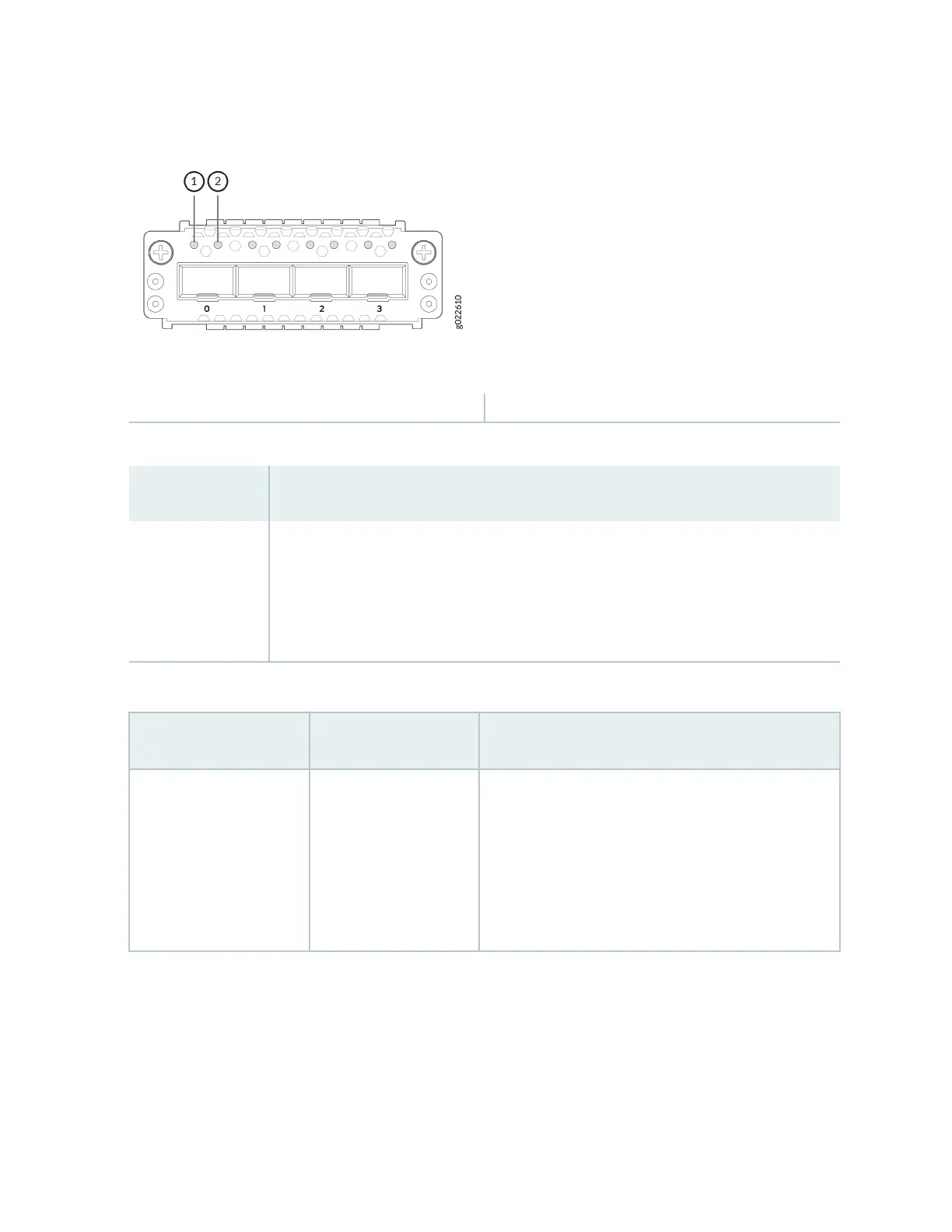
Figure 57: LEDs on the 4x10GbE SFP+ Extension Module Ports
1—
Link acvity LED
2—
Status LED
Table 39: Link Acvity LED on the Extension Module Ports
Color State and Descripon
Green
• On steadily—The port and the link are acve, but there is no link acvity.
• Blinking—The port and the link are acve, and there is link acvity.
• Unlit—The port is not acve.
Table 40: LEDs on the 1x100GbE QSFP28 Extension Module Port
LED Color State and Descripon
The LED on the extreme
le
Green
• On steadily—A 100-Gbps link is established, but
there is no link acvity.
• Blinking—A 100-Gbps link is established, and there
is link acvity.
• O—There is no link.
76