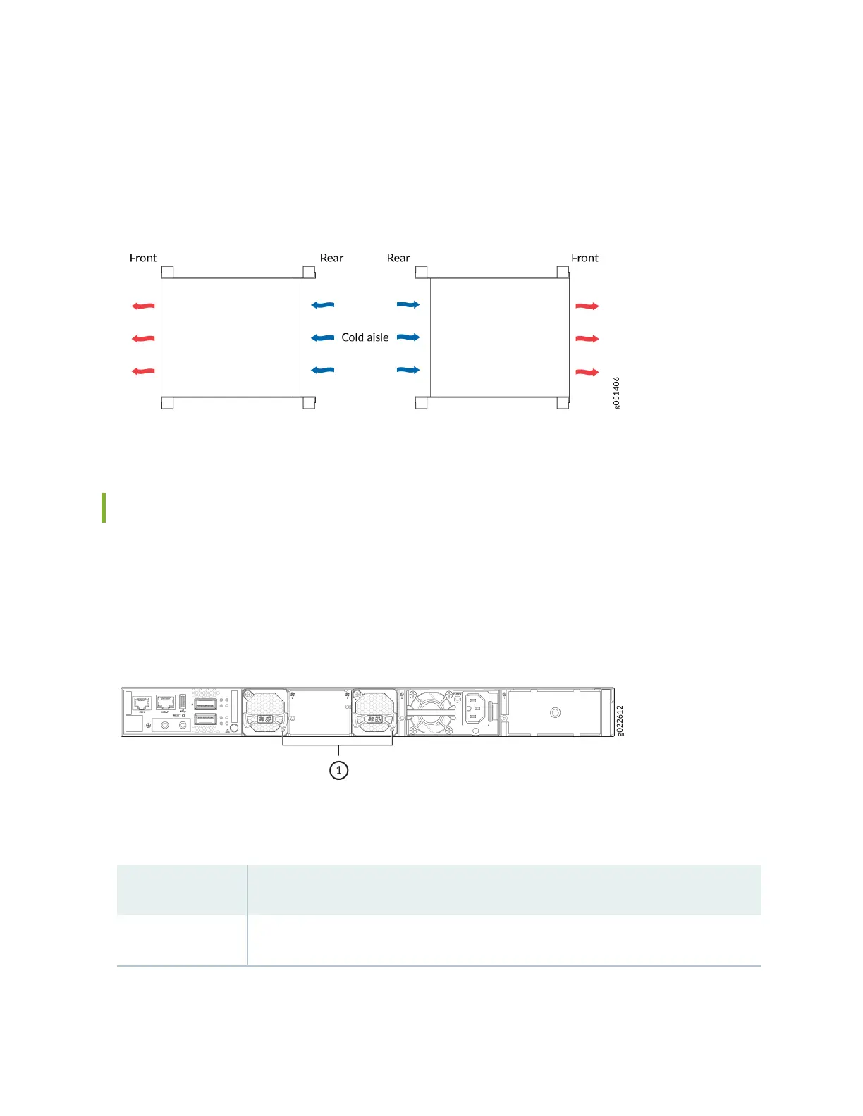
Posion the switch with back-to-front airow in such a manner that the AIR IN labels on the fan
modules and power supplies are next to the cold aisle (see Figure 73 on page 88).
Figure 73: Deployment of Switches with Back-to-Front Airow Through the Switch Chassis
Fan Module Status
Each fan module has a status LED on it that indicates the status of the fan module (see Figure 74 on
page 88).
Figure 74: Fan Module LED
Table 43 on page 88 describes the LED.
Table 43: Fan Module Status LED
State Descripon
Lit green The fan module is funconing normally.
88