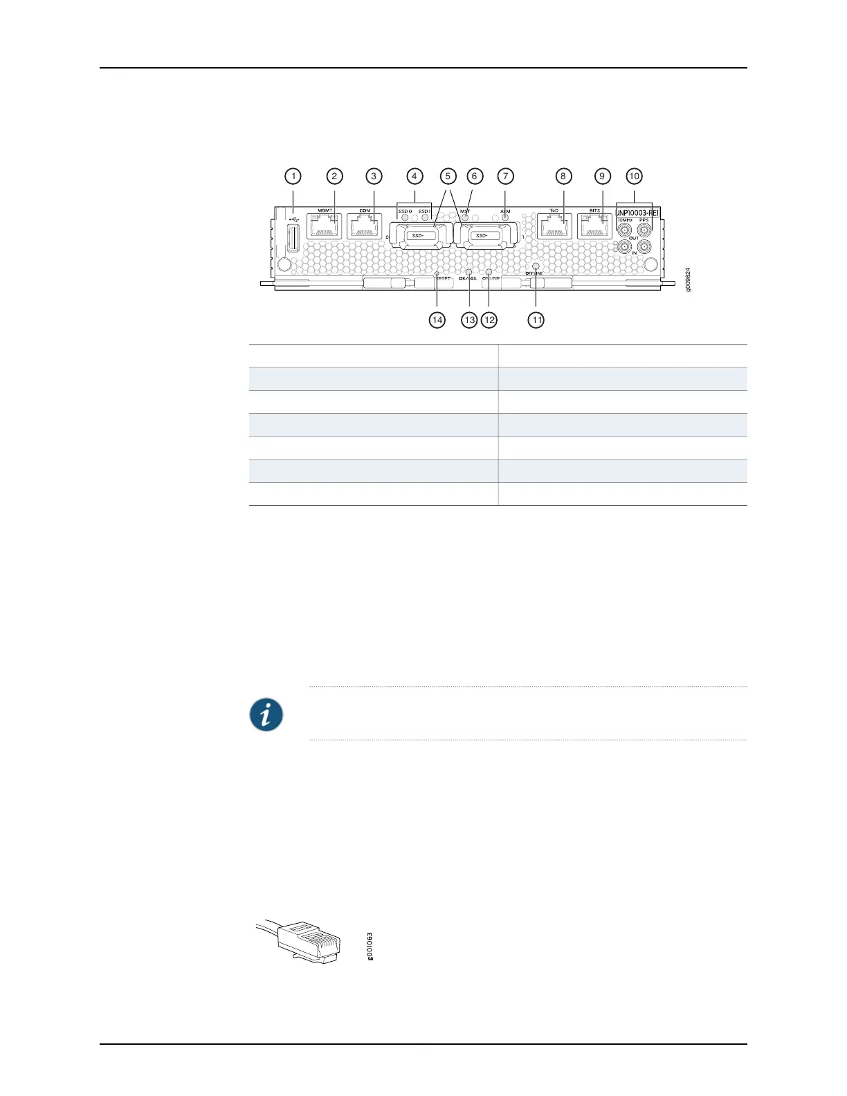
Figure 9: Routing and Control Board (RCB) Ports
g009824
1 2 3 4 5 6 7 8 9 10
11121314
8—1—
Time of day (ToD) port with LEDs
USB port
9—2—
BITS port with LEDsManagement (MGMT) port
10—3— Clocking ports
Console (CON) port
11—4—
OFFLINE button
SSD LEDs
12—5—
ONLINE LEDSSD slots (0 and 1)
13—6—
OK/FAIL LEDMaster (MST) LED
14—7—
RESET buttonAlarm (ALM) LED
•
Connecting the Router to a Network for Out-of-Band Management on page 11
•
Connecting the Router to a Console Device on page 12
•
Connecting the Router to External Clocking and Timing Devices on page 13
Connecting the Router to a Network for Out-of-Band Management
To connect the RCB to a network for out-of-band management, connect an Ethernet
cable with RJ-45 connectors to the MGMT port on the RCB interface. One Ethernet cable
is provided with the router. To connect to the MGMT port on the RCB faceplate:
NOTE: Use shielded CAT5e cable for the CON and MGMT ports on the RCB.
1. Turn off power to the management device.
2. Plug one end of the Ethernet cable (Figure 10 on page 11 shows the connector) into
the MGMT port on the RCB interface.
3. Plug the other end of the cable into the network device.
Figure 10: Out-of-Band Management Cable Connector
11Copyright © 2017, Juniper Networks, Inc.
Connecting the Router to a Network for Out-of-Band Management