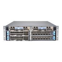
To connect the router to a BITS external clocking device:
1. Attach an electrostatic discharge (ESD) grounding trap on your bare wrist, and connect
the strap to one of the ESD points on the chassis.
2. Plug one end of the RJ-45 cable into the internal clock port on the craft interface.
3. Plug the other end of the RJ-45 cable into the BITS external clocking device.
4. Verify that the LEDs for the BITS port are lit steadily green.
5. Configure the port. See Configuring Clock Synchronization Interface on MX Series Routers.
Table 5: BITS Port on the RCB
DescriptionLabelCallout (See Figure 9)
Building-Integrated Timing Supply
(BITS) clock interface port with LED.
BITS9
Step 5: Connect Power Cables
Depending on the configuration, your router uses either AC or DC power supplies. Perform
the appropriate procedures for each power supply in your router. The power supplies are
hot-insertable and are field-replaceable units (FRUs). You can install up to six power
supplies in an MX10003 router. The power supplies install in the rear of the chassis in the
slots provided.
WARNING: You must ground the router before connecting either the AC
power cord or the DC power cable.
CAUTION: Do not mix AC and DC power supplies in the same chassis.
•
Connect Power to an AC Router on page 15
•
Connect Power to a DC Router on page 17
Connect Power to an AC Router
Table 6: MX10003 AC Power System Input Voltage
SpecificationItem
Operating range: 90–264 VACAC input voltage
15Copyright © 2017, Juniper Networks, Inc.
Step 5: Connect Power Cables

 Loading...