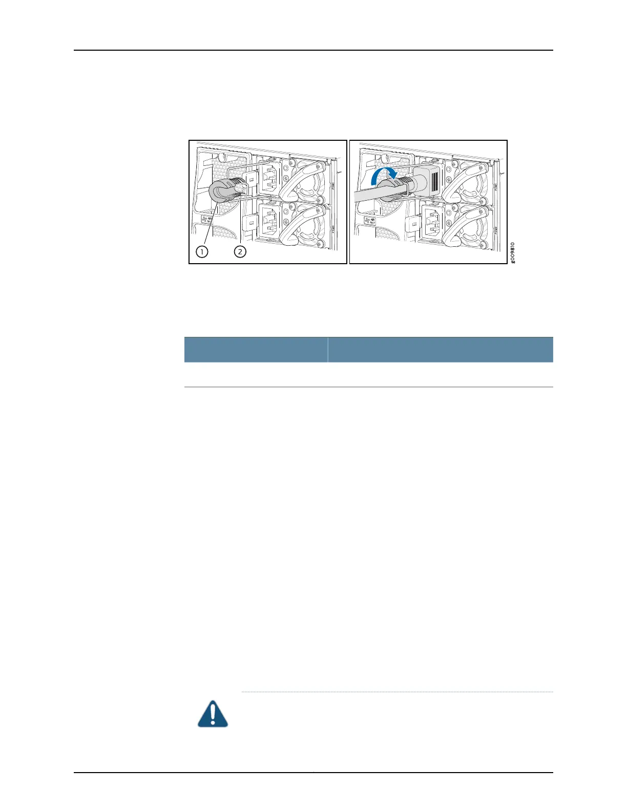
Figure 14: Connecting an AC Power Cord to an MX10003 AC Power Supply
Connect Power to a DC Router
Table 7: MX10003 DC Power System Input Voltage
SpecificationItem
Operating range: –40 through –72 VDCDC input voltage
1. Switch off the dedicated customer-site circuit breakers. Ensure that the voltage across
the DC power source cable leads is 0 V and that there is no chance that the cable
leads might become active during installation.
2. Verify that the DC power cables are correctly labeled before making connections to
the power supply. In a typical power distribution scheme where the return is connected
to chassis ground at the battery plant, you can use a multimeter to verify the resistance
of the –48V and RTN DC cables to chassis ground:
•
The cable with very large resistance (indicating an open circuit) to chassis ground
is –48V.
•
The cable with very low resistance (indicating a closed circuit) to chassis ground is
RTN.
3. Remove the screws from the terminals.
4. Secure each power cable lug to the terminal with the screw (see Figure 15 on page 19).
Apply between 5 lb-in. (0.6 Nm) and 6 lb-in. (0.7 Nm) of torque to the screw. Do not
overtighten the nut. (Use a number 2 Phillips screwdriver.)
a. Secure the positive (+) DC source power cable lug to the RTN (return) terminal.
b. Secure the negative (–) DC source power cable lug to the –48V (input) terminal.
CAUTION: Ensure that each power cable lug seats flush against the surface
of the terminal block as you are tightening the screws. Ensure that each
17Copyright © 2017, Juniper Networks, Inc.
Connect Power to a DC Router