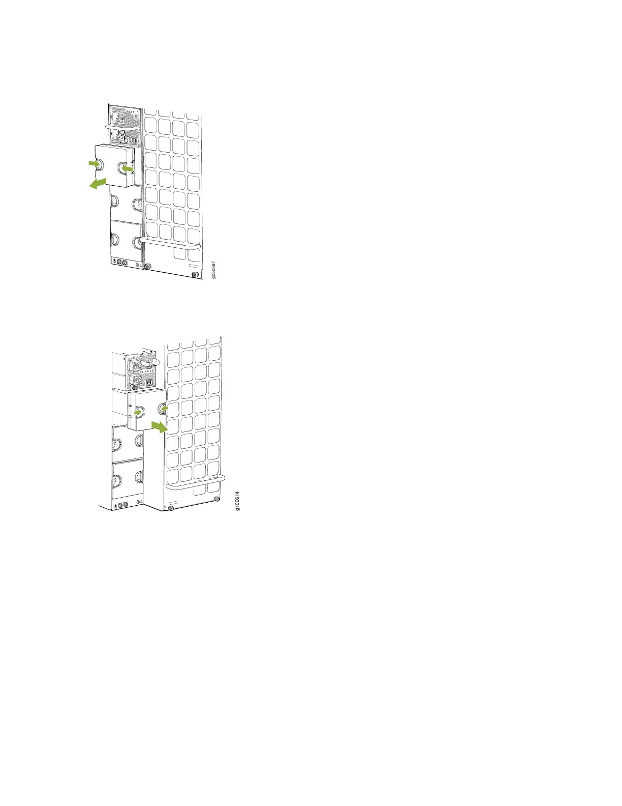
Figure 120: Removing the PSU Cover Panel on an MX10008
Figure 121: Removing the Power Supply Cover Panel on an MX10016
13. Unscrew the captive screw in the counterclockwise direction by using the Phillips (+) screwdriver,
number 1.
14. Pull the captive screw away from the faceplate of the power supply to release the latch. You can install
the power supplies in any slot labeled PSU 0 through PSU 5 (top to bottom) on an MX10008 and PSU 0
through PSU 9 on an MX10016.
15. Using both hands, place the power supply in the power supply slot on the rear of the router.
16. Slide the power supply straight into the chassis until the power supply is fully seated in the slot. Ensure
the power supply faceplate is flush with any adjacent power supply faceplates or power supply cover
panels (see Figure 122 on page 227 and Figure 123 on page 227).
226