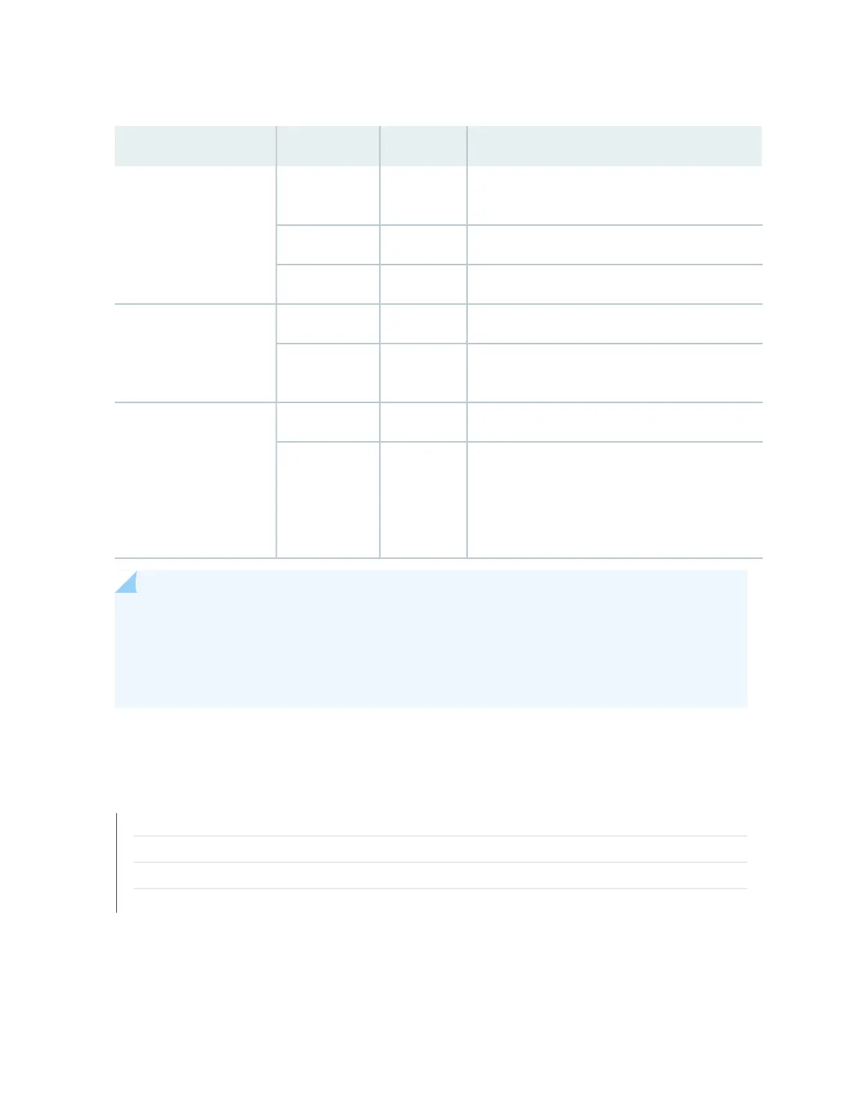
Table 16: LEDs on a JNP10K-PWR-AC Power Supply
DescriptionStateColorLED
Indicates that the AC power input voltage is not
within normal operating range.
BlinkingYellowINP1 (INP0 in CLI output)
or INP2 (INP1 in CLI
output)
AC is within operating range (200–240 VAC).SolidGreen
The power supply is switched off.UnlitDark
DC power output is within normal operating range.SolidGreenPWR OK
AC power output is out of the normal operating
range.
BlinkingYellow
Power supply is functioning normally.UnlitDarkFAULT
Power supply has failed and must be replaced. Or,
only one input is powered and the enabled router
for the input that is not powered is set to ON. See
How to Install a JNP10K-PWR-AC Power Supply for
more information about the enable routers.
SolidRed
NOTE: If the INP1 or INP2 LED and the PWR OK LED are unlit, the AC power cord is not installed
properly or the power supply has failed.
If the INP1 or INP2 LED is lit and the PWR OK LED is unlit, the AC power supply is not installed
properly or the power supply has an internal failure.
SEE ALSO
JNP10K-PWR-AC Power Specifications | 105
Power Requirements for MX10008 Components
MX10000 Power Cables Specifications | 107
Connecting AC Power to an MX10000 | 163
71